

Improvements in or relating to dip tubes
A dip tube, container technology, applied to a single handheld device, liquid distribution, packaging, etc., can solve the problems of propellant exhaustion, interruption of required liquid product distribution, insufficient propellant, etc., and achieve the effect of low manufacturing cost
- Summary
- Abstract
- Description
- Claims
- Application Information
AI Technical Summary
Problems solved by technology
Method used
Image

Examples
Embodiment Construction
[0090] In the following description of the drawings, like reference numerals are used to designate like or corresponding parts in different drawings.
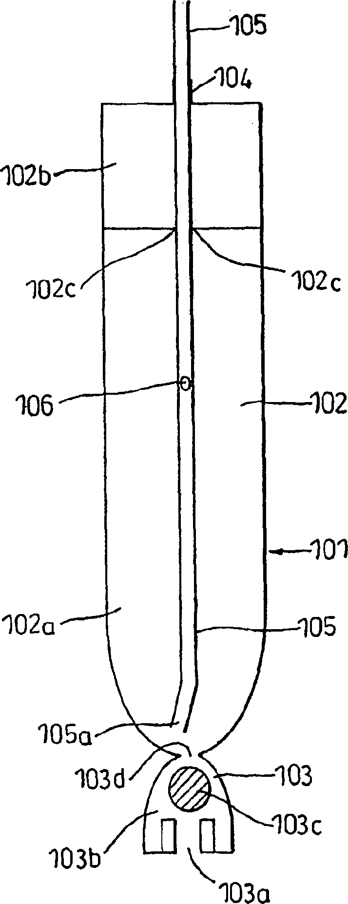
[0091] figure 1 Represents a first embodiment 101 of a device according to the invention, which is adapted to be placed inside a container and to allow liquid stored in said container to flow from the inside of the container into said device, and from said device to the container outlet, where the liquid Dispensed through a nozzle arrangement (not shown).
[0092] The device 101 is made of flexible or elastically deformable plastic and comprises a body forming an internal chamber 102; an inlet 103 having an opening 103a through which the contents of the container can enter the chamber; an outlet tube 105 for dispensing The device is connected to an outlet valve or a nozzle structure actuated by a pump or trigger, allowing liquid to flow from the chamber 102 to a container outlet (not shown).
[0093] Chamber 102 includes an u...
PUM
 Abstract
Description
Claims
Application Information