
Force value transfer device for anti-shock pressure meter
A technology of transmission device and pressure gauge, which is applied in the direction of measuring device, measuring fluid pressure, measuring the elastic deformation force through the measuring gauge, etc. It can solve the problems of high scrap rate, poor recovery, and surface roughness affecting the strength and accuracy of the fork spring, etc. question
- Summary
- Abstract
- Description
- Claims
- Application Information
AI Technical Summary
Problems solved by technology
Method used
Image

Examples
Embodiment Construction
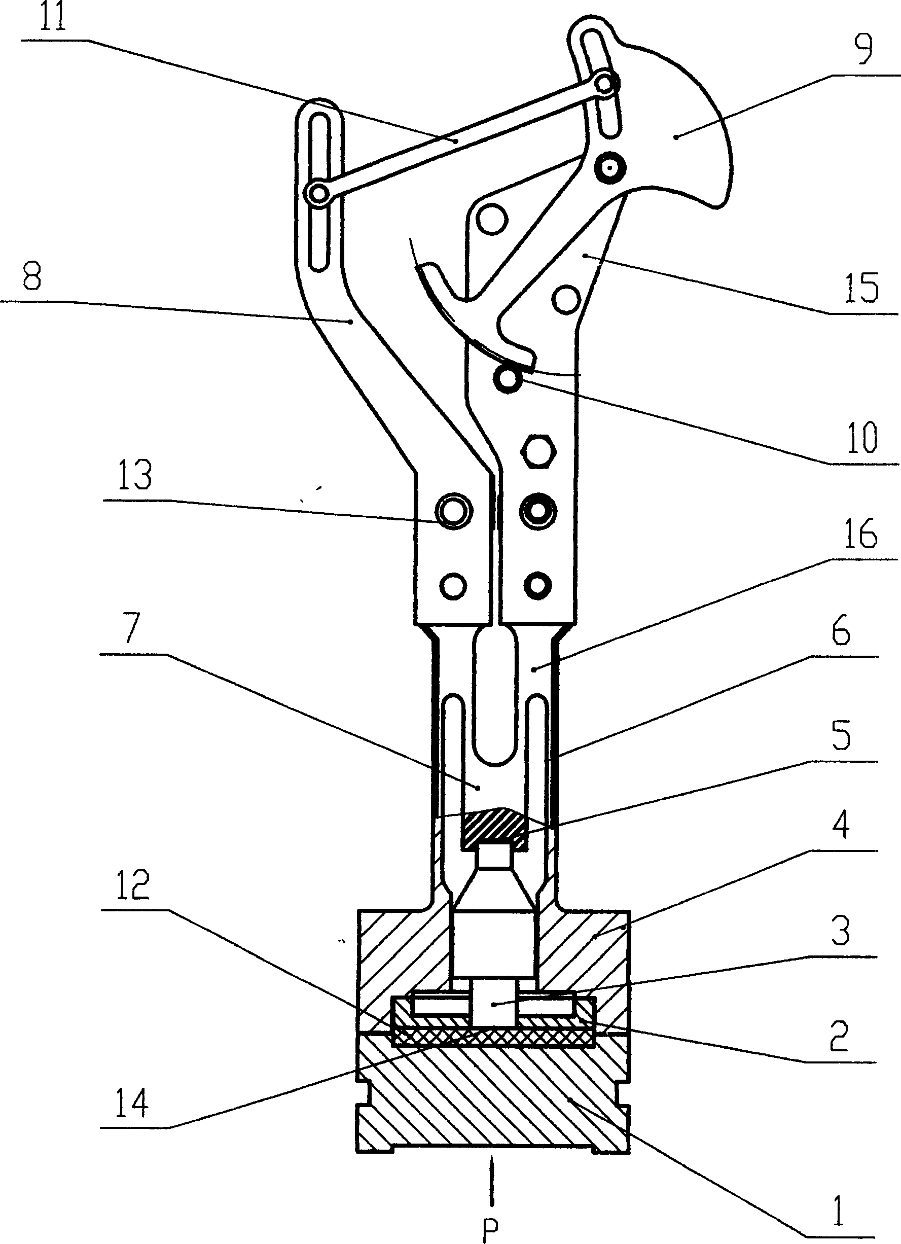
[0008] figure 1 As shown, for the present invention to create a specific embodiment of an anti-seismic pressure gauge force value transmission device, it includes a damping assembly 1, a fork spring 16, and an enlarged indicator mechanism. The fork spring 16 is composed of a fork spring seat 4 and a reed 6 , center top spring 7 is formed, and left and right reed 6 is connected on the fork spring seat 4, and center top spring 7 is positioned between left and right reed 6 and is connected as a whole with left and right reed 6, and described fork spring The seat 4 is provided with a guide hole for the ejector rod and a positioning hole for the diaphragm, and correspondingly provided with the ejector rod 3 and the diaphragm 2. The output end 5 of the ejector rod is matched with the central top spring 7, and the input end 14 is matched with the center hole of the diaphragm 2. The damping assembly 1 cooperates with the end surface of the diaphragm 2 through the gasket 12 . Describe...
PUM
| Property | Measurement | Unit |
|---|---|---|
| thickness | aaaaa | aaaaa |
| thickness | aaaaa | aaaaa |
Abstract
Description
Claims
Application Information