Fire grate plate and corresponding incinerate fire grate and refuse incinerate equipment

A technology for incinerators and grates, which is applied in the direction of combustion equipment, lighting and heating equipment, grates of hollow furnace bars, etc.

Inactive Publication Date: 2006-01-18
DOOSAN LENTJES GMBH
View PDF2 Cites 8 Cited by
  • Summary
  • Abstract
  • Description
  • Claims
  • Application Information

AI Technical Summary

Problems solved by technology

However, the cost for such a water-cooled system is much higher than that for an air-cooled system

Method used


Image

  • Fire grate plate and corresponding incinerate fire grate and refuse incinerate equipment
  • Fire grate plate and corresponding incinerate fire grate and refuse incinerate equipment
  • Fire grate plate and corresponding incinerate fire grate and refuse incinerate equipment

Examples


Embodiment Construction

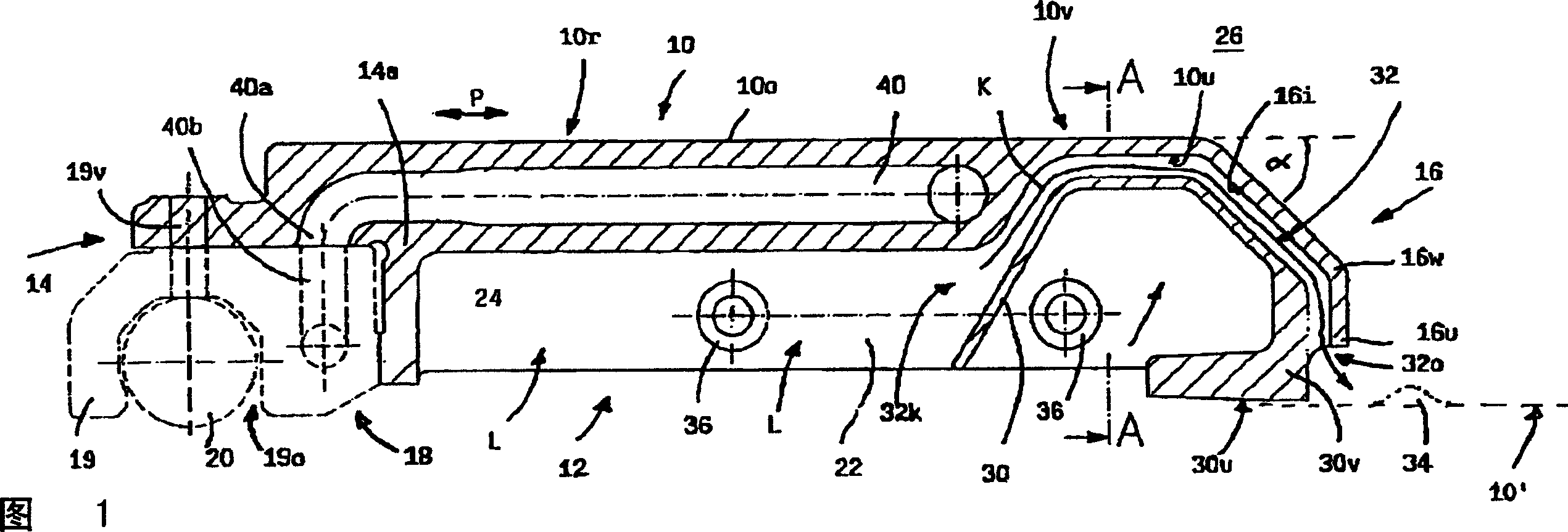
[0048] The basic design of the grate plate is described below in conjunction with FIG. 1: the grate plate has an upper side 10, a lower side 12, a rear long side 14, a front long side 16 and two wide sides that cannot be seen due to the chosen section line . The upper region 10 o of the upper side 10 is implemented in a planar manner. The second front long side 16 is angled a (about 45°) relative to the upper surface 10o and then angled at 16w.

[0049] The underside of the grate plate adjacent to the first (rear) long side 14 comprises a recess 18 extending in the longitudinal direction (into the plane of the protrusion) in which a connecting element 19 comprising a further recess 19o is placed, And wherein the round rod 20 is located in this additional recess and (indirectly) supports the grate plate. The grate plate shown in FIG. 1 can be moved in the direction of the arrow P with the help of the round rod 20 . The connecting element 19 is described in more detail below....


PUM


Abstract

The invention relates to a grate plate used for burning grates, including a burning grate of the grate plate and solid waste burning equipment which is equipped with the burning grate.

Description

technical field [0001] The invention relates to a grate plate for an incineration grate, an incineration grate comprising such a grate plate and a waste (waste) incineration plant having such an incineration grate. Background technique [0002] The most important part of a waste incineration plant is the incineration grate, which is arranged horizontally or in an inclined manner and on which the material to be incinerated, such as refuse, is conveyed from a first end to what is commonly called Burn out the second end of the grate. The required incineration air is pressurized through the incineration grate. For this purpose, corresponding holes are provided in the incineration grate. This means that the material to be incinerated (waste) is essentially processed in three steps, namely "drying", subsequent "incineration" and finally conversion into slag. These three steps can be controlled independently if desired. [0003] There are various types of incineration grates, i...

Claims


Application Information

Patent Timeline
Patent Type & Authority Applications(China)
IPC IPC(8): F23H3/00F23G5/44
CPCF23H17/12F23H3/02F23H2900/03021F23H3/04
Inventor A·埃泽尔
Owner DOOSAN LENTJES GMBH
Why Eureka
Try Eureka