Switch power supply and its lossless absorption circuit

A lossless absorption, switching power supply technology, applied in the direction of converting irreversible DC power input to AC power output, can solve the problems of limited application range, slow switching speed, power supply cannot be no-load, etc., to expand the adjustment range and reduce spikes voltage, the effect of reducing selection requirements

Active Publication Date: 2006-02-15
航天智讯新能源(山东)有限公司
View PDF0 Cites 3 Cited by
  • Summary
  • Abstract
  • Description
  • Claims
  • Application Information

AI Technical Summary

Problems solved by technology

However, this kind of circuit has the following disadvantages: due to the leakage inductance of the transformer and the stray inductance in the actual circuit, the switch Q1 will generate an induced voltage on the leakage inductance and stray inductance when it is cut off, so that the switch is easily damaged due to overvoltage
[0018] In this case, the loss of D2 is also greatly increased, which reduces the performance of the lossless absorption circuit. In order to solve this problem, it is necessary to choose a diode with high withstand voltage and fast switching speed, but according to the characteristics of the diode, the higher the withsta

Method used


Image

  • Switch power supply and its lossless absorption circuit
  • Switch power supply and its lossless absorption circuit
  • Switch power supply and its lossless absorption circuit

Examples


Example Embodiment

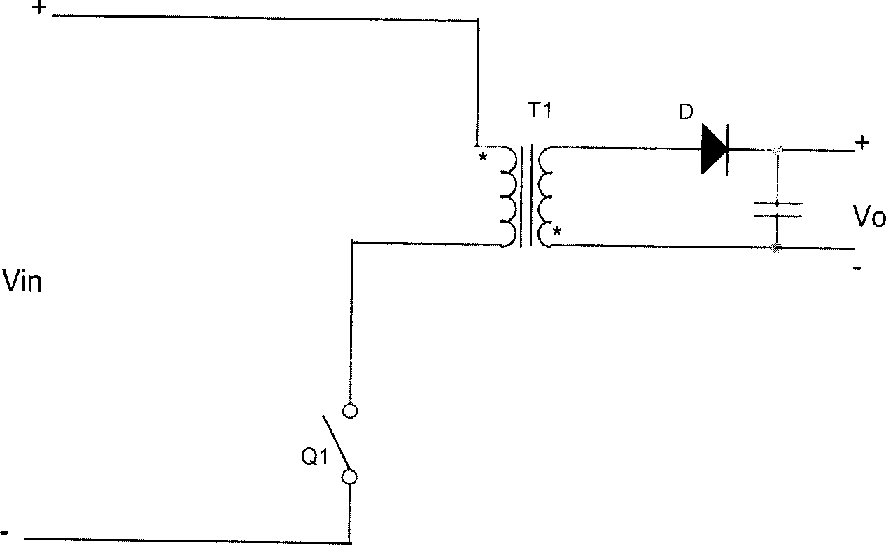
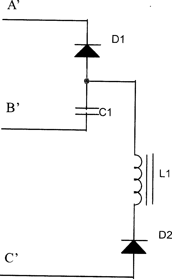
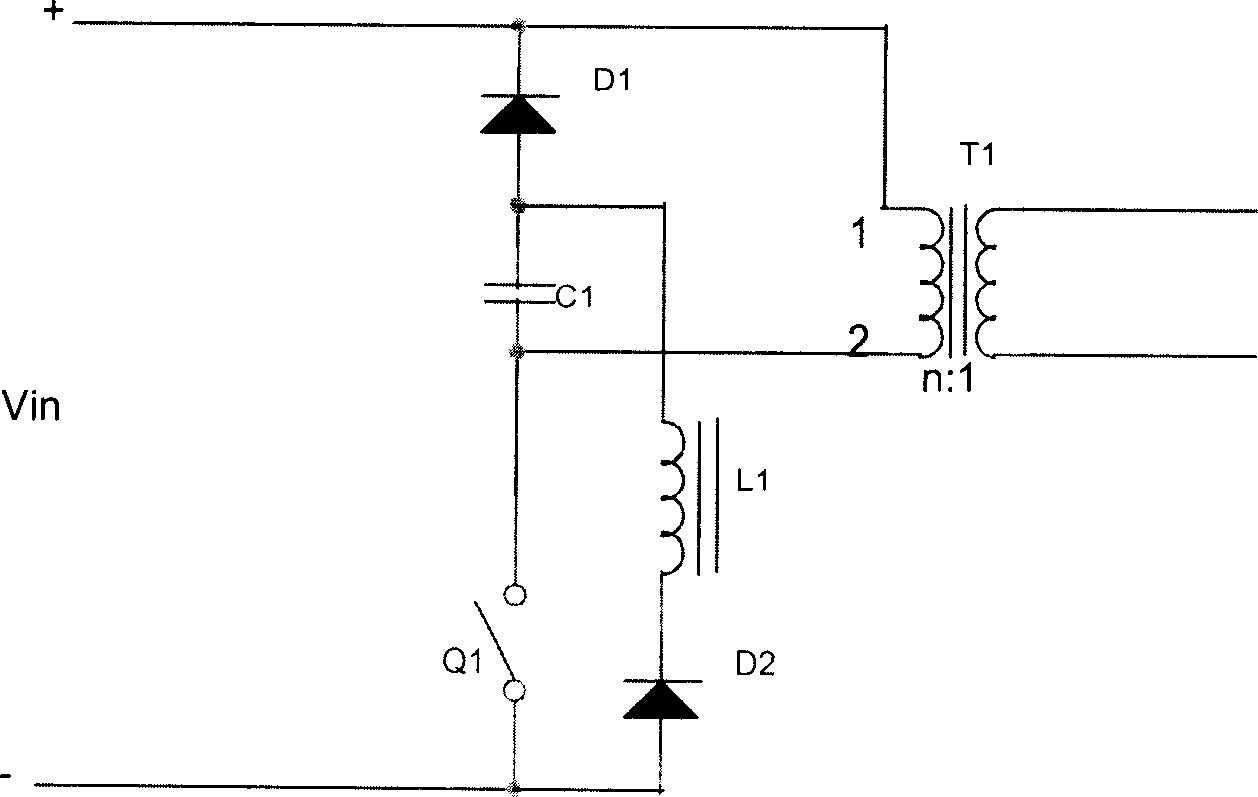
[0040] see Figure 9 to Figure 11, the lossless snubber circuit of this embodiment is applied to a single-ended flyback switching power supply. The lossless snubber circuit has three interface ports A, C, and B, and the three interface ports A, C, and B are respectively connected to the positive end, The negative terminal of the input power supply and the switching element. The lossless snubber circuit includes a first diode D1, a second diode D2, a clamping circuit D3, a capacitor C1 and an inductor L1. The cathode of the first diode D1 is connected to the positive end of the input power supply, the anode of the first diode D1 is connected to one end of the inductor L1 and one end of the capacitor C1, and the other end of the inductor L1 is connected to the cathode of the second diode D2 , the anode of the second diode D2 is connected to the negative terminal of the input power supply (or grounded), and the other terminal of the capacitor C1 is used to connect to the switchi...


PUM


Abstract

The non-loss absorber circuit comprises a first diode with cathode connected to input source positive end and anode connected to one end of inductance and capacitor, a second diode with anode connected to input source negative end, a capacitor with another end connected to switch element, an inductance with another end connected to cathode of second diode, and a clamping circuit with one end connected to source positive end and another end connected to second diode cathode to clamp the voltage of second diode on determined voltage when the switch element shuts. This invention decreases spike voltage and loss.

Description

【Technical field】 [0001] The invention relates to the field of switching power supplies. 【Background technique】 [0002] see figure 1 , which is a basic circuit of a single-ended flyback switching power supply. In this circuit, the input DC voltage is chopped into an alternating square wave voltage by controlling the on-off of the switch Q1, which is coupled to the secondary side through a transformer and then passed through The rectifier diode D rectifies to obtain the transformed voltage. However, this kind of circuit has the following disadvantages: due to the leakage inductance of the transformer and the stray inductance in the actual circuit, the switch Q1 will generate an induced voltage on the leakage inductance and stray inductance when it is cut off, so that the switch is easily damaged due to overvoltage . [0003] In order to reduce the voltage stress on the switch, an absorption or snubber circuit will be added to the switching device in the actual circuit, su...

Claims


Application Information

Patent Timeline
IPC IPC(8): H02M7/48
Inventor 黄传东易强顾锦筛蔡子海
Owner 航天智讯新能源(山东)有限公司
Why Eureka
Try Eureka