Rider restriction device of two-wheeled vehicle

一种限制装置、二轮车的技术,应用在行人/乘员安全布置、自行车安全装备、摩托车等方向

Inactive Publication Date: 2006-03-01
HONDA MOTOR CO LTD
View PDF0 Cites 2 Cited by
  • Summary
  • Abstract
  • Description
  • Claims
  • Application Information

AI Technical Summary

Problems solved by technology

[0004] The technology described in Patent Document 1 presupposes that there is a support member capable of supporting the shock absorbing member in front of the occupant's knee, so it is not suitable for vehicles such as motorcycles that do not have a support member in front of the occupant's knee.

Method used


Image

  • Rider restriction device of two-wheeled vehicle
  • Rider restriction device of two-wheeled vehicle
  • Rider restriction device of two-wheeled vehicle

Examples


Embodiment Construction

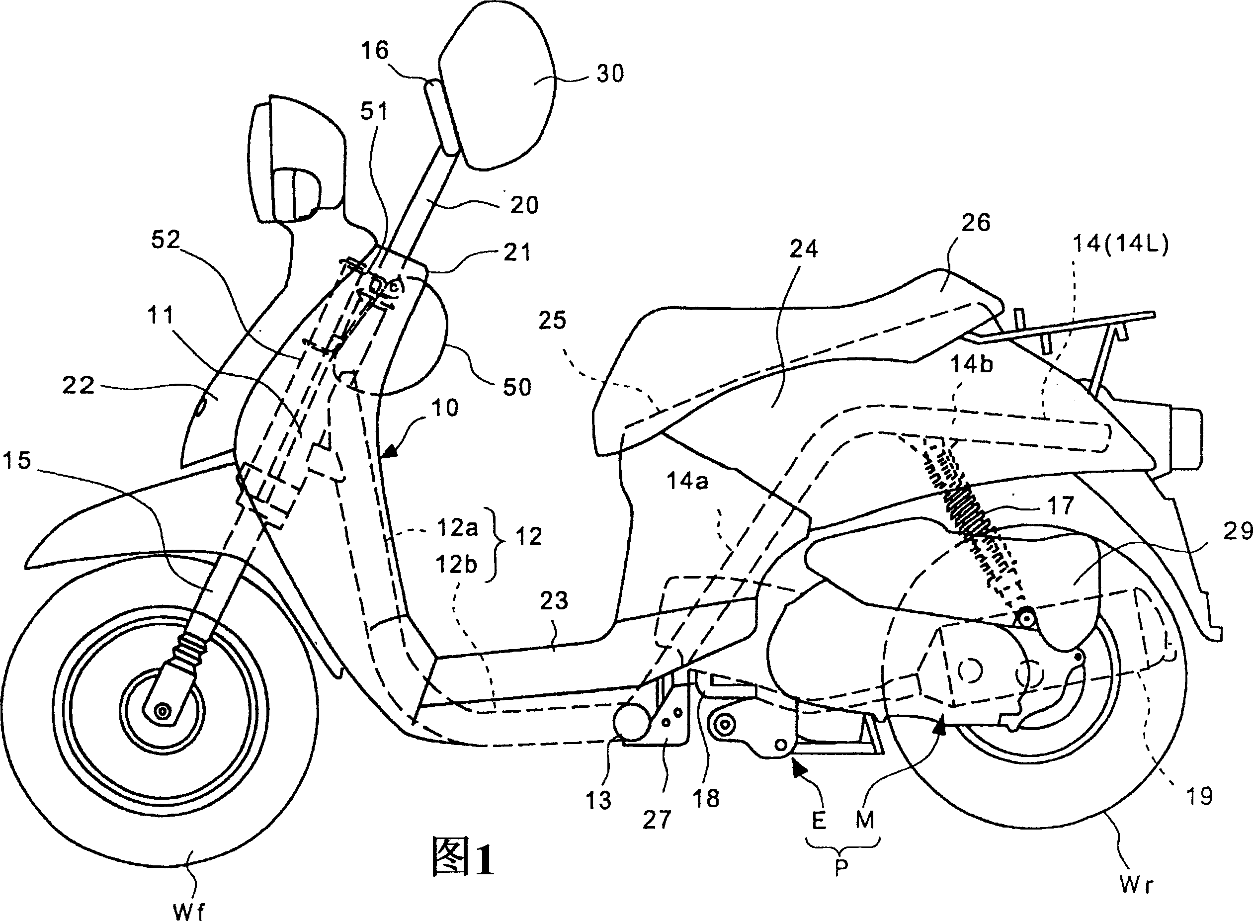
[0031] Next, preferred embodiments of the present invention will be described with reference to the drawings. Fig. 1 is a side view of a small automatic two-wheeled vehicle to which the occupant restraint device of the present invention is applied, in which a body frame 10 is mainly composed of the following components: a main frame tube 12 with a head tube 11 fixed at the front end; A pair of left and right rear frame tubes 14 ( 14L, 14R) provided at both ends of the cross tube 13 are respectively connected to the cross tube 13 and the front end of which the rear end portion of the frame tube 12 is fixed at right angles and horizontally.

[0032] The main frame tube 12 is formed by integrally connecting a down frame portion 12a and a down frame portion 12b. The rear end of the frame portion 12a extends substantially horizontally rearward. The above-mentioned cross pipe 13 is extended in the left-right direction of the vehicle body frame 10, and the rear end part of the main ...


PUM


Abstract

To provide a rider restraining device of a two wheeler easy to apply to a small vehicle and capable of restraining a load added to a rider without necessarily enlarging a pad. A connecting member 53 is fixed on a lower part of a head pipe 11, and a pair of left and right pad supporting pipes (52 L, R) is erected by directing backward diagonally upward along a handle post 11 from this connecting member 53. A pair of left and right knee pads (50 L, R) is installed on an upper part of each of the pad supporting pipes 52 respectively in a posture directing a knee part of the rider through plate members (51 L, R). A load absorbing function to move the load added to the rider by absorbing a forward load exceeding a pre-determined standard value when it is added to the knee part pads 50 is given to the pad supporting pipes 52.

Description

technical field [0001] The present invention relates to an occupant restraint device of a two-wheel vehicle, in particular to an occupant restraint device of a two-wheel vehicle which restricts the movement of the lower body of the occupant to the front of the vehicle body. Background technique [0002] As a technology for restricting the movement of the occupant to the front of the vehicle body in an automatic two-wheeled vehicle, Patent Document 1 discloses the following technology: As a technology for restricting the movement of the lower body of the occupant to the front of the vehicle body in a four-wheeled vehicle, a A shock absorbing member is provided at a position facing the occupant's knees. [0003] Patent Document 1: Patent Publication No. 2705775 [0004] The technique described in Patent Document 1 presupposes a support member capable of supporting the shock absorbing member in front of the occupant's knees, so it is not applicable to vehicles such as motorcyc...

Claims


Application Information

Patent Timeline
Patent Type & Authority Applications(China)
IPC IPC(8): B62J27/00
CPCB60R21/04B60R2021/0051B62J27/00B60R2021/0088B62K11/00
Inventor 角田和彦仓田德博秋山秀树村田裕荻野孝
Owner HONDA MOTOR CO LTD
Why Eureka
Try Eureka