
Occupant restraining device for two-wheel vehicle

A restraint device, a technology for two-wheeled vehicles, applied in the direction of bicycle safety equipment, motorcycles, bicycles, etc.

Inactive Publication Date: 2008-12-03
HONDA MOTOR CO LTD
View PDF6 Cites 0 Cited by
  • Summary
  • Abstract
  • Description
  • Claims
  • Application Information

AI Technical Summary

Problems solved by technology

[0004] In the technology described in Patent Document 1, it is necessary to ensure a space for mounting the airbag unit and its control unit near the instrument panel, and it is necessary to install an acceleration sensor, so it is difficult to apply it to small motorcycles.

Method used


Image

  • Occupant restraining device for two-wheel vehicle
  • Occupant restraining device for two-wheel vehicle
  • Occupant restraining device for two-wheel vehicle

Examples


Embodiment Construction

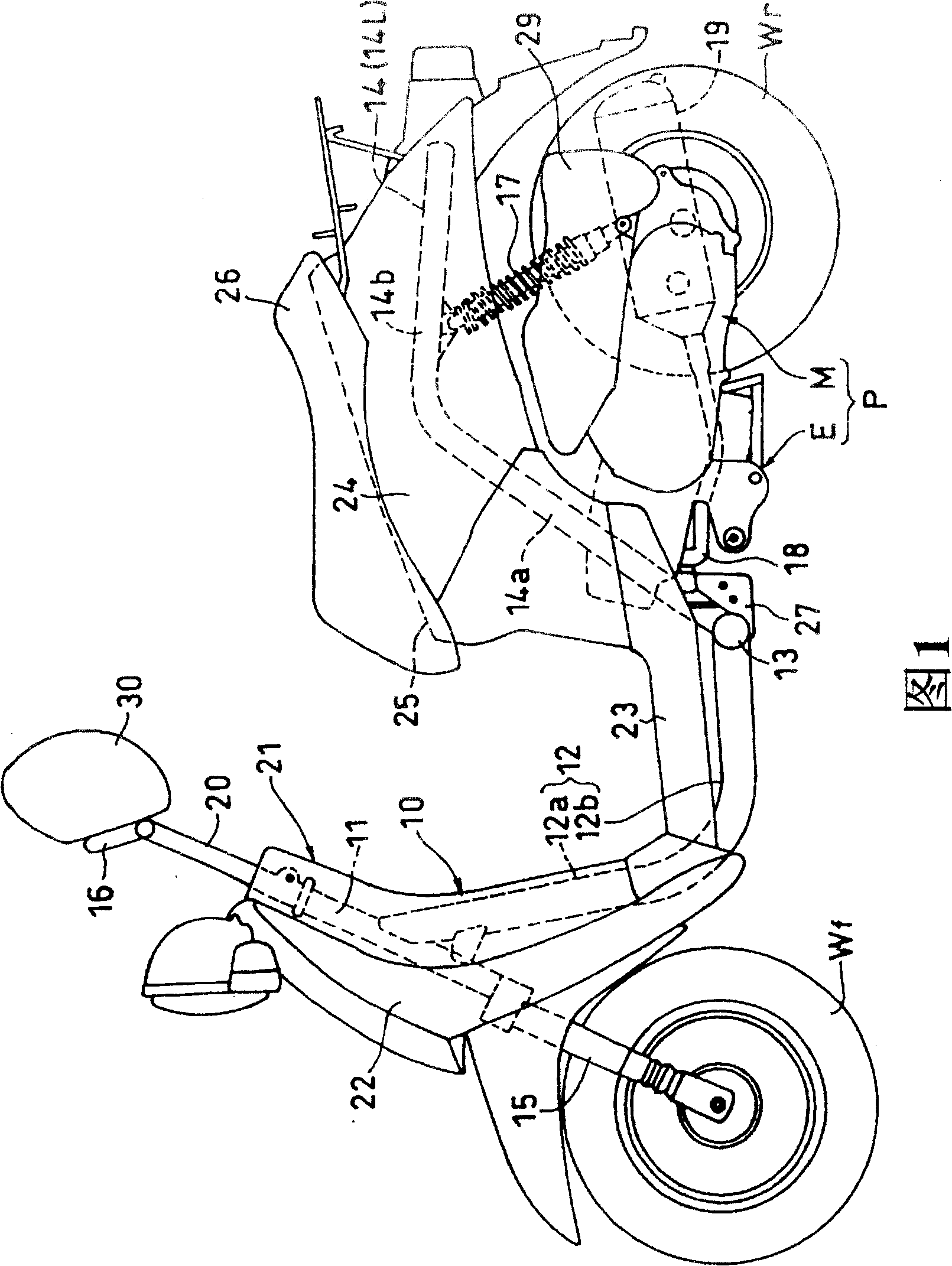
[0025] Hereinafter, embodiments of the present invention will be described with reference to the drawings. Fig. 1 is a side view of a small automatic two-wheeled vehicle to which the occupant restraint device of the present invention is applied. The vehicle body frame 10 has: a main frame tube 1 with a head tube 11 fixed at the front end, fixed to the main frame at right angles and horizontally. A pair of left and right rear frame tubes 14 ( 14L, 14R) provided at both ends of the cross tube 13 are respectively connected to the cross tube 13 on the rear end portion of the tube 12 and the front end.

[0026] The above-mentioned main frame tube 12 is formed by integrally connecting a lower frame portion 12a and a lower frame portion 12b, wherein the lower frame portion 12a is inclined backward and downward from the head pipe 11, and the lower frame portion 12b is formed from The rear end of the down frame portion 12a extends substantially horizontally rearward. The cross pipe 13...


PUM


Abstract

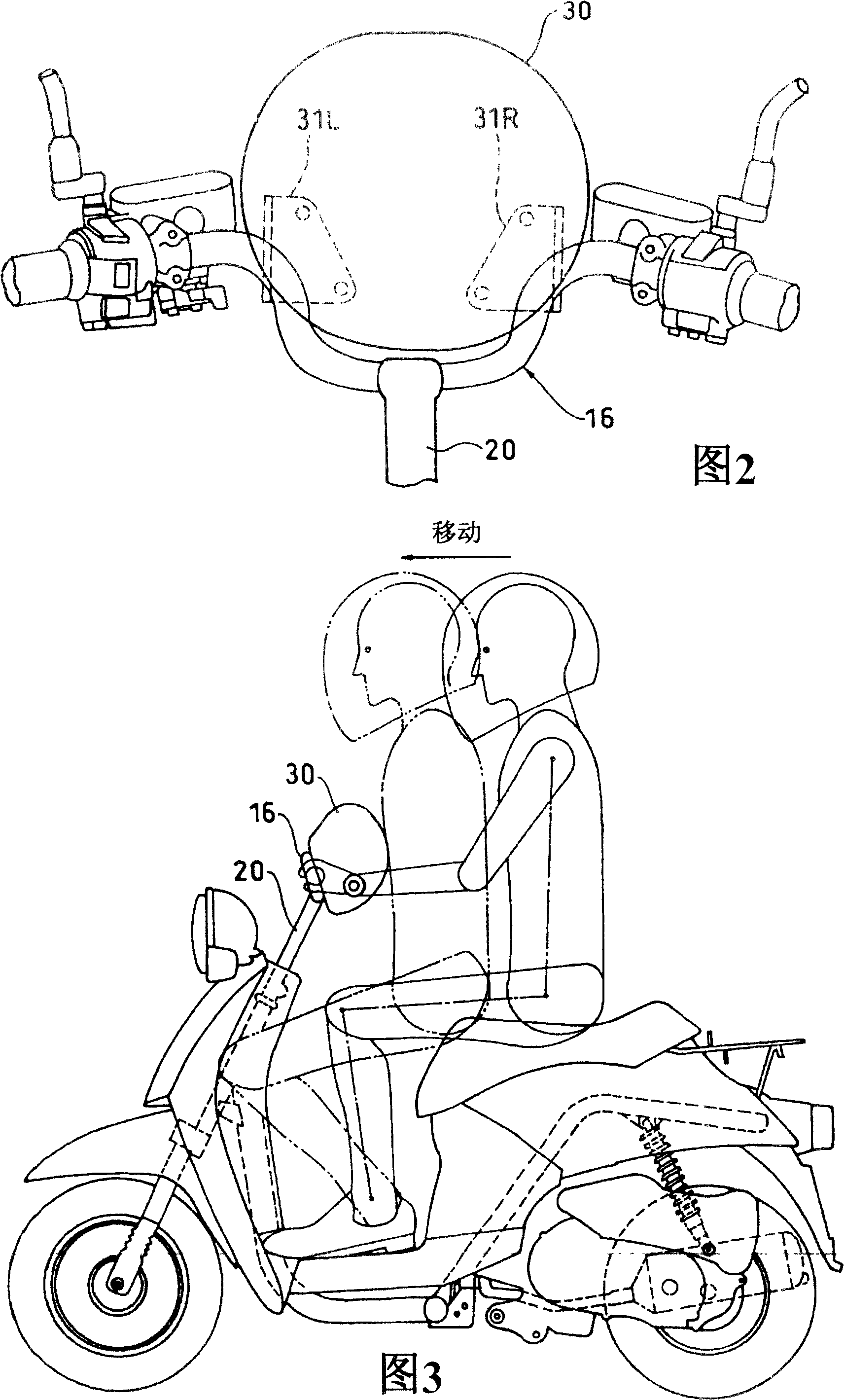
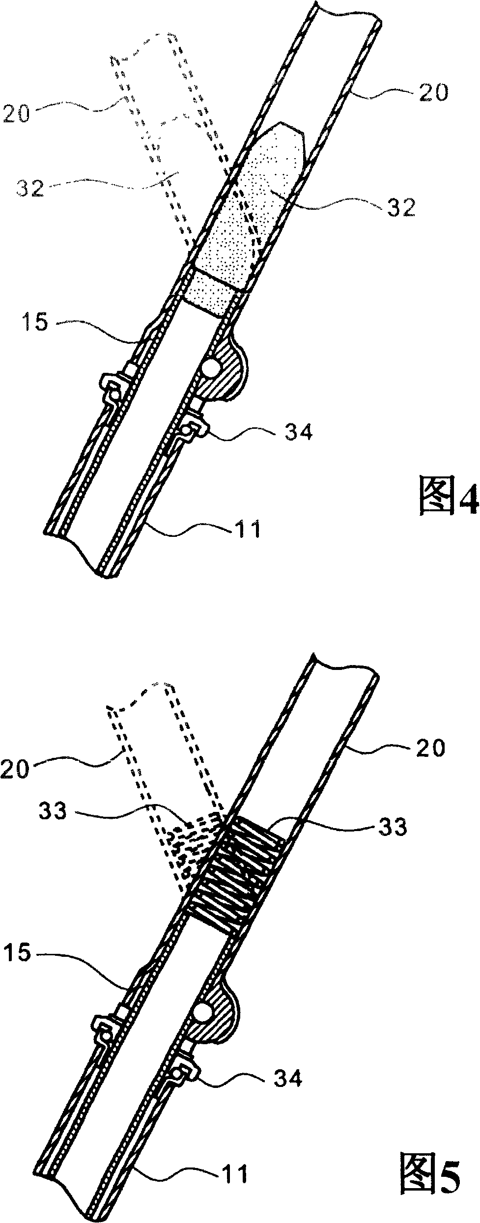
The invention provides a rider control device for a two wheeler easily applied to a small vehicle and capable of suppressing load applied to a rider without enlarging a pad. This rider control device for the two wheeler comprises a control pad 30 mounted to a handlebar 16 to face the rider; a front fork 15 supported to be steerable by a head pipe 11; a handle pipe 20 for connecting the handlebar 16 to the front fork 15; and an elastic member 32 for absorbing forward load applied to the control pad 30 to plastically deform the handle pipe 20 to incline forward in a predetermined position.

Description

technical field [0001] The present invention relates to an occupant restraint device of a two-wheel vehicle, in particular to an occupant restraint device of a two-wheel vehicle which restrains the occupant from moving forward of the vehicle body. Background technique [0002] In a motorcycle, Patent Document 1 discloses a technique of disposing an airbag near a dashboard of the motorcycle and activating the airbag when an impact is detected, as a technique for restricting movement of an occupant to the front of the vehicle body. [0003] Patent Document 1: Japanese Unexamined Patent Publication No. 11-278342 [0004] In the technology described in Patent Document 1, it is necessary to secure a space for mounting the airbag unit and its control unit near the instrument panel, and to install an acceleration sensor, so it is difficult to apply it to small motorcycles. Contents of the invention [0005] In order to solve the above-mentioned problems in the prior art, the pre...

Claims


Application Information

Patent Timeline
Patent Type & Authority Patents(China)
IPC IPC(8): B62K21/12B62J27/00B62K27/00
CPCB62J27/00B62K2202/00B62K21/12B62K11/14
Inventor 角田和彦仓田德博秋山秀树村田裕荻野孝
Owner HONDA MOTOR CO LTD
Learn More