Solid state lighting device

A technology for solid-state lamps and light-emitting modules, which is applied to lighting devices, components of lighting devices, cooling/heating devices of lighting devices, etc., can solve the problems of insufficient thermal design, impracticality, and increased cost.

Inactive Publication Date: 2006-05-10
NXGEN TECH
View PDF0 Cites 18 Cited by
  • Summary
  • Abstract
  • Description
  • Claims
  • Application Information

AI Technical Summary

Problems solved by technology

However, these thermal designs are inadequate, impractical, or both
Most designs require power conversion from source voltage AC to low voltage DC, which greatly increases cost and makes their designs more complex, while some prior art does not address power or electric coupling of components
Furthermore, much of the prior art has focused on using discrete components to expand the typical light emission pattern of an LED light bulb, rather than focusing on the need for light bulbs with various light emission patterns

Method used


Image

  • Solid state lighting device
  • Solid state lighting device
  • Solid state lighting device

Examples


Embodiment Construction

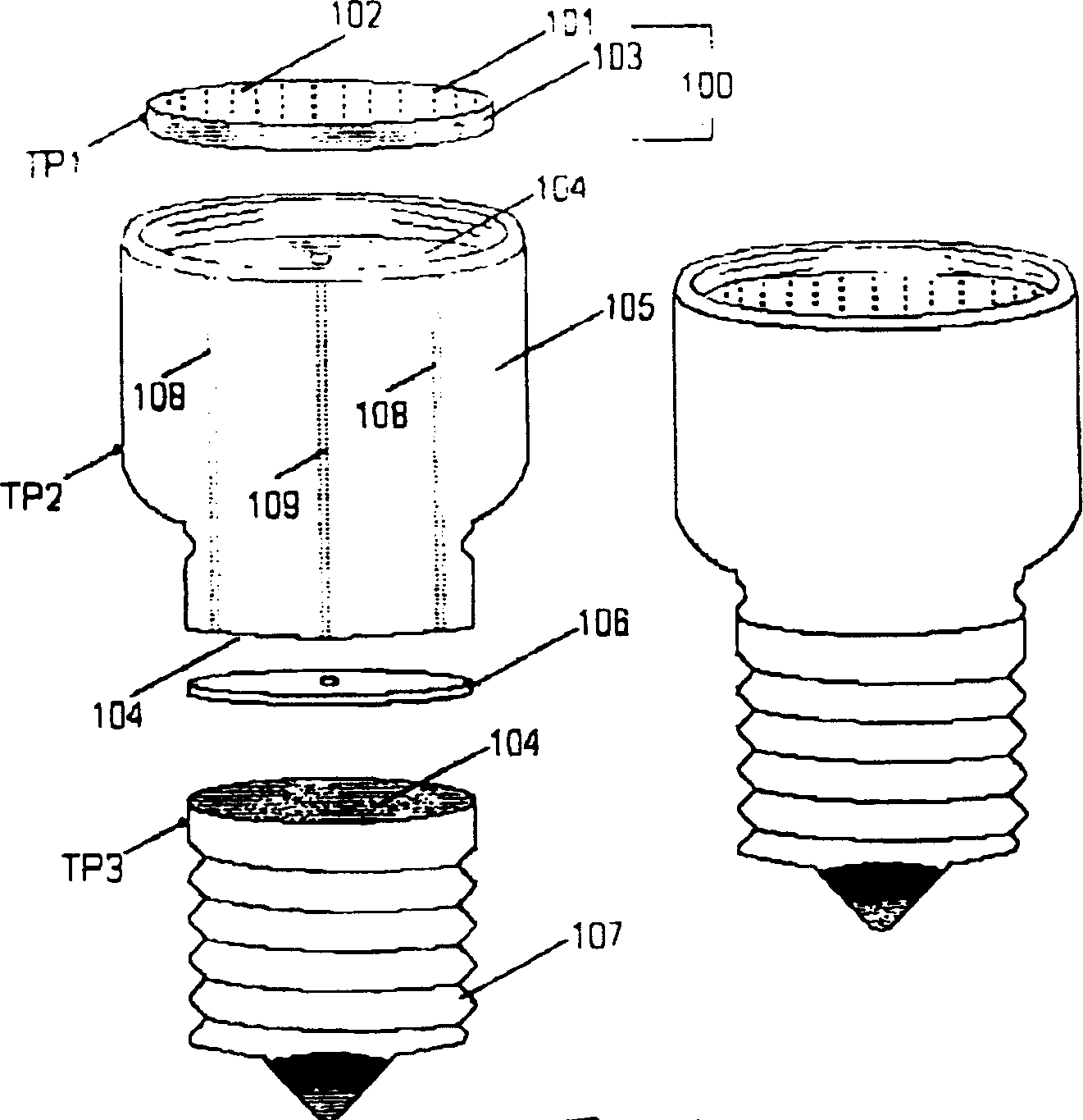
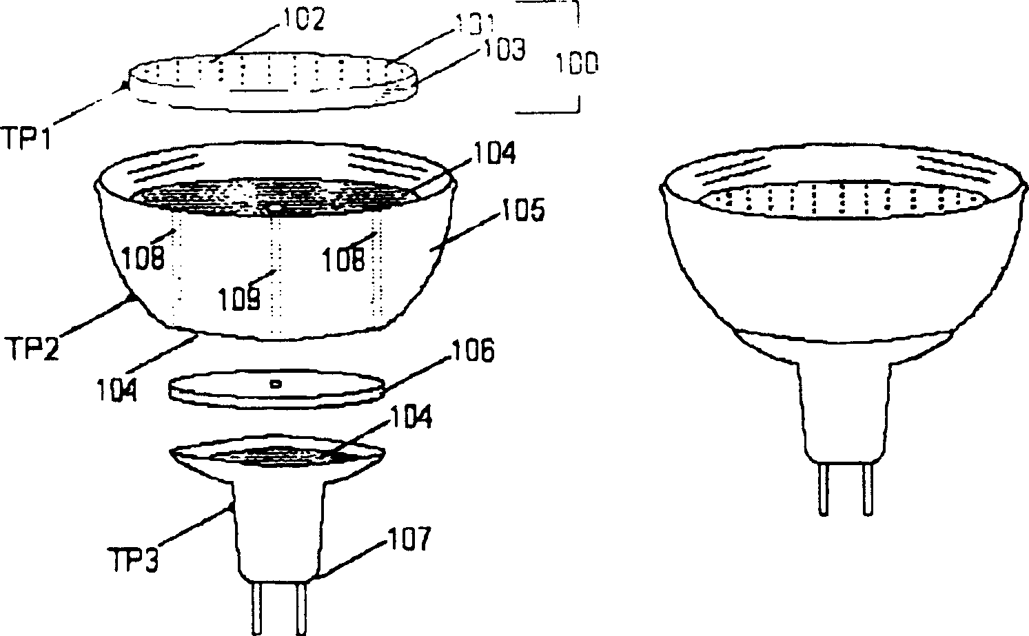
[0025] as attached Figure 1a , 2a , 3a and 5, a light emitting module (lighting module) 100 includes LED chips 101, and these LED chips 101 are directly fixed on a PCB (printed circuit board) using a traditional chip-on-board method known in the art. ) on 102. The PCB 102 is directly bonded to a backer plate / heat sink 103 made of aluminum, copper, ceramic or other materials with good heat transfer properties.

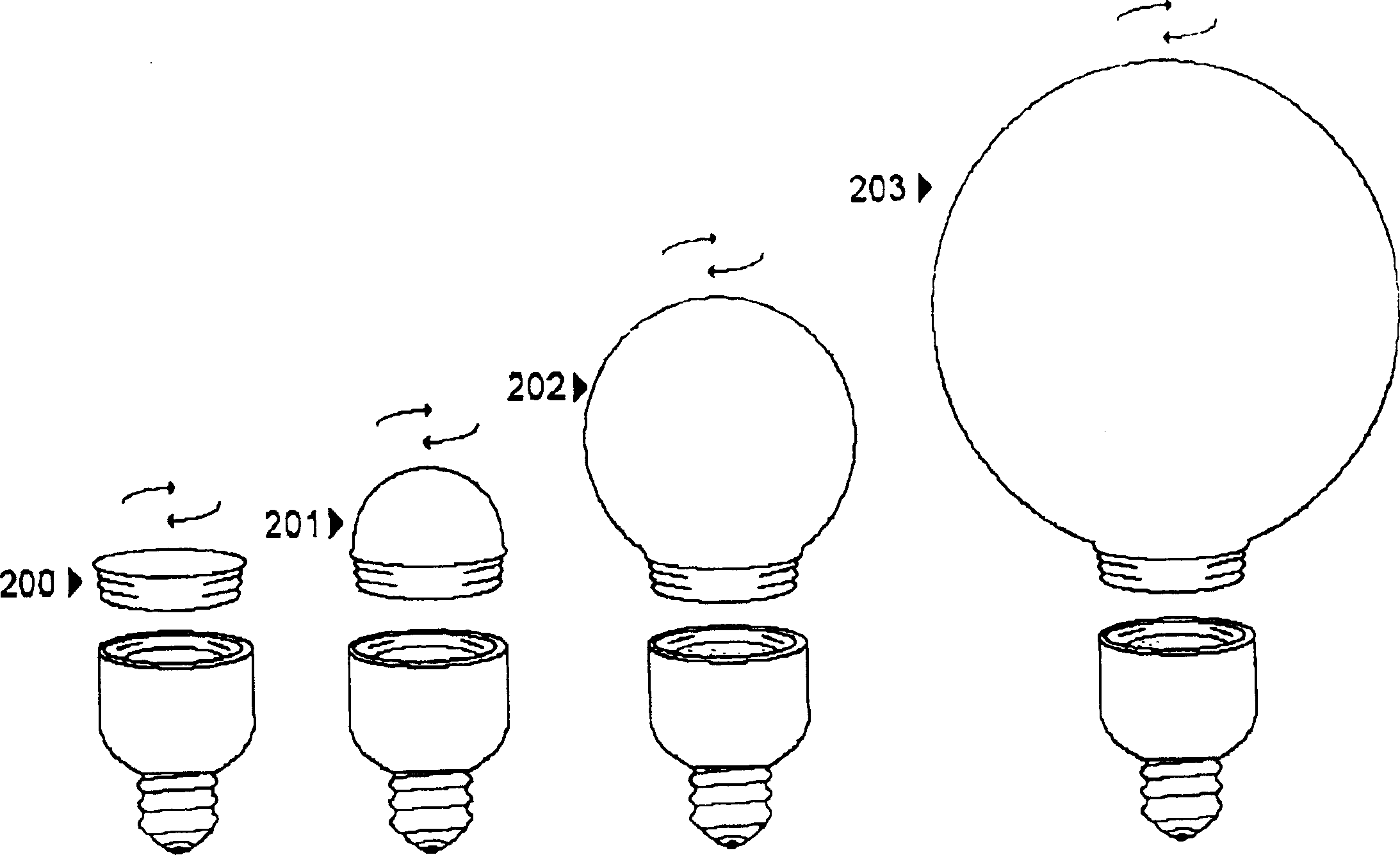
[0026] It should be noted that the total surface area of ​​the light emitting module 100, especially the backing plate / heat sink 103 can be made smaller or larger and thicker to match the density and number of LED chips 101 and the total module power requirements (in watts) Unit) related thermal performance requirements. It should also be noted that the lighting module 100 can be fabricated using multiple planes that are electrically connected together. Test samples made using circular, single planar lighting modules exhibited uniform light distribution when fitted ...


PUM


Abstract

Solid state (light emitting diode) lamps of various configurations have improved thermal management capabilities by providing a direct thermal path from the multiple LED chips to the screw cap (standard 100-240VAC lamp socket) or power connector. The control circuit is arranged opposite to the printed circuit board and the LED chip with respect to the heat sink, so that the heat sink is between the printed circuit board and the control circuit. LED chips are powered using a high voltage / high current structure. The light radiation pattern can be infinitely adjusted (from very wide to very narrow) through a series of easily interchangeable lenses. Solid-state lights with very high illuminance can be mass-produced quickly and at a relatively low cost. ESD protection can be added to protect LED chips from electrostatic discharge damage.

Description

[0001] This application is a non-provisional patent application of US Provisional Patent Application No. 60 / 625,163, filed November 5, 2004, which prior application is hereby incorporated by reference. technical field [0002] The present invention relates to light emitting diode lamps, and more particularly, to easily mass-producible light emitting diode lamps having an adjustable integrated thermal management system located outside the encapsulating bulb or lens, with maximum Heat transfer area, designed to operate at high currents (and thus higher powers) and capable of emitting high luminous intensity with an infinitely adjustable beam radiation pattern . Background technique [0003] In the prior art, light emitting diodes (LEDs) and other semiconductor light sources have not been successfully or economically used to illuminate physical spaces. Earlier prior art described LED light sources as indicator lights, or as low voltage coupled with low input current, low volta...

Claims


Application Information

Patent Timeline
Patent Type & Authority Applications(China)
IPC IPC(8): F21S2/00F21S4/00F21V5/04F21V23/00F21V29/00F21W131/00F21Y101/02H01R33/09
CPCF21V3/00F21V3/02F21V17/002F21V17/12F21V23/006F21V29/74F21K9/23F21K9/232F21K9/238F21Y2115/10H01L2224/48091H01L2224/73265H01L2924/00014
Inventor 戴维·艾伦
Owner NXGEN TECH
Why Eureka
Try Eureka