Plasma display panel

A plasma and display panel technology, applied in the direction of AC plasma display panels, gas discharge electrodes, tube structure components, etc., can solve the problems of low luminous efficiency of PDP devices

Inactive Publication Date: 2006-06-07
SAMSUNG SDI CO LTD
View PDF0 Cites 0 Cited by
  • Summary
  • Abstract
  • Description
  • Claims
  • Application Information

AI Technical Summary

Problems solved by technology

As a result, only a part of the phosphors formed in the discharge cells can be excited, and thus the PDP device as a whole will have low luminous efficiency

Method used


Image

  • Plasma display panel
  • Plasma display panel
  • Plasma display panel

Examples


Embodiment Construction

[0038] Various embodiments of the present invention will now be described in detail with reference to the accompanying drawings to enable those of ordinary skill in the relevant art to make the invention. However, the present invention is not limited to the embodiments described below, and thus various changes and modifications can be made. In the drawings, descriptions of parts not related to the present invention will be omitted for clarity. Also, the same or similar components are denoted by the same reference numerals throughout the specification.

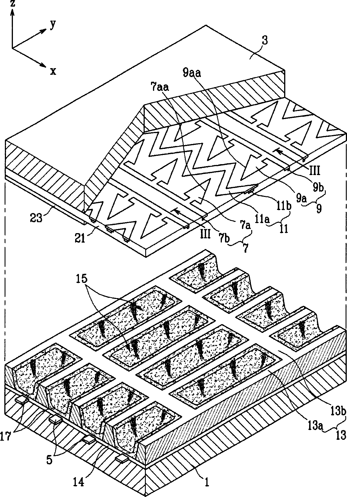
[0039] figure 1 is a partially exploded perspective view showing a plasma display panel according to an embodiment of the present invention.

[0040] refer to figure 1 , The PDP according to this embodiment has a first substrate 1 (hereinafter referred to as a rear substrate) and a second substrate 3 (hereinafter referred to as a front substrate), which are arranged to face each other at a predetermined interval and bonded t...


PUM


Abstract

The present invention provides a plasma display panel device including discharge electrodes having non-straight edge lines, which improves luminous efficiency. The plasma display panel device includes: a first substrate and a second substrate disposed facing each other; barrier ribs disposed between the first substrate and the second substrate to separate a plurality of discharge cells; indoor. The device also includes: address electrodes extending in a first direction; first electrodes and second electrodes extending in a second direction crossing the first direction; third (scanning) electrodes each provided with There is a constant spacing between and from the first electrode and the second electrode. At least one of the first electrode, the second electrode and the third electrode has an edge line extending obliquely to the first direction.

Description

technical field [0001] The present invention relates to a display panel, and more particularly, to a configuration of electrodes of a plasma display panel device. Background technique [0002] In general, plasma display panel (hereinafter referred to as PDP) devices display images using gas discharge, and have excellent display performance including high display capacity, brightness, contrast, and short afterimage and wide viewing angle. [0003] In a PDP device, a voltage is applied between sustain electrodes and scan electrodes, thereby generating gas discharge between these electrodes. Then, the phosphor is excited by vacuum ultraviolet rays caused by gas discharge, and images are realized by visible light generated when the phosphor is stabilized. [0004] The PDP device has a front substrate and a rear substrate coupled to each other with barrier ribs provided therebetween. The front substrate has sustain electrodes and scan electrodes. The ...

Claims


Application Information

Patent Timeline
IPC IPC(8): H01J11/12H01J11/24H01J11/26
CPCH01J11/24H01J11/32H01J2211/245H01J2211/323H01J11/22
Inventor 金泰佑金贞男田炳玟李正斗
Owner SAMSUNG SDI CO LTD
Why Eureka
Try Eureka