Scroll compressor

A scroll compressor and a moving scroll technology, applied in the field of scroll compressors, can solve problems such as reducing heat exchange efficiency

Active Publication Date: 2006-07-26
TOYOTA IND CORP
View PDF1 Cites 14 Cited by
  • Summary
  • Abstract
  • Description
  • Claims
  • Application Information

AI Technical Summary

Problems solved by technology

If lubricating oil is brought into the external cooling circuit, for example, the lubricating oil sticks to the inner wall surface of the gas cooler or evaporator, thereby reducing the efficiency of heat exchange

Method used


Image

  • Scroll compressor
  • Scroll compressor
  • Scroll compressor

Examples


Embodiment Construction

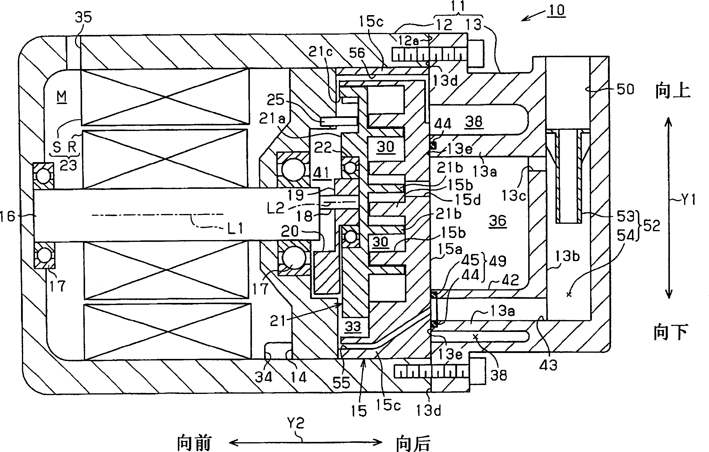
[0014] An electric scroll compressor applied to the external refrigerant circuit of an automobile air conditioner according to the present invention will be described below with reference to the accompanying drawings. In the explanation below, figure 1 The direction indicated by the Y1 arrow in the middle is the vertical direction of the electric scroll compressor 10 , including upward and downward directions. Depend on figure 1 The Y2 arrow indicates the lateral direction of the electric scroll compressor 10, including forward and backward directions. In this embodiment, carbon dioxide is used as the refrigerant in the external refrigerant circuit.

[0015] Such as figure 1 As shown, the housing 11 of the electric scroll compressor 10 includes a front housing 12 and a rear housing 13 . The front case 12 and the rear case 13 are connected to each other. The shaft support 14 and the fixed scroll 15 are fixedly fitted in the casing 11 . In detail, the shaft support 14 and ...


PUM


Abstract

A scroll compressor includes a housing, a discharge passage, a rotary shaft, a fixed scroll, a movable scroll, an oil separator and an oil reservoir for compressing refrigerant gas containing lubricating oil. The housing has a rear housing which has a partition wall. The discharge passage is formed in the housing. The discharge passage has a discharge chamber, a discharge hole and an accommodation chamber. The discharge chamber and the accommodation chamber are communicated with each other through the discharge hole. The oil separator is provided in the accommodation chamber. The oil separator has a separation member and an oil reserved area. The oil reservoir is defined around an entire circumference of the partition wall which defines the discharge chamber therein. The oil reservoir is formed so as to communicate with the oil reserved area of the oil separator.

Description

technical field [0001] The invention relates to a scroll compressor, which has a plurality of movable and volume-reduced compression chambers, and refrigerant gas is sucked from the suction chamber to the A compression chamber, in which the refrigerant gas is then compressed and discharged into the discharge chamber. Background technique [0002] A conventional electric scroll compressor used in an automobile air conditioner has a housing formed such that a front housing and a rear housing are connected to each other. The fixed scroll is fixed on the front casing, the movable scroll is opposite to the fixed scroll, and the two scrolls are installed in the front casing. In addition, there is a motor cavity inside the front case, and the electric motor is disposed in the motor cavity. A suction passage is formed at the lower end of the front case to communicate with the motor cavity. [0003] There is also a suction cavity inside the front housing, which is shaped to commun...

Claims


Application Information

Patent Timeline
Patent Type & Authority Applications(China)
IPC IPC(8): F04C18/02F04C29/02
Inventor 小出达也水藤健木村一哉纪井法道
Owner TOYOTA IND CORP
Why Eureka
Try Eureka