Application method of high dielectric microwave composite material on antenna made

A technology with composite functions and application methods, applied in antennas, antenna parts, waveguide devices, etc., can solve problems such as increased surface wave loss, poor antenna radiation efficiency, narrow bandwidth, etc., and achieve excellent performance and high radiation efficiency with the effect of buff

Inactive Publication Date: 2006-11-22
上海联能科技有限公司 +2
View PDF0 Cites 28 Cited by
  • Summary
  • Abstract
  • Description
  • Claims
  • Application Information

AI Technical Summary

Problems solved by technology

But for antenna applications, as the dielectric constant increases, the surface wave loss continues to increase, the radiation effic

Method used


Image

  • Application method of high dielectric microwave composite material on antenna made
  • Application method of high dielectric microwave composite material on antenna made
  • Application method of high dielectric microwave composite material on antenna made

Examples


Embodiment 1

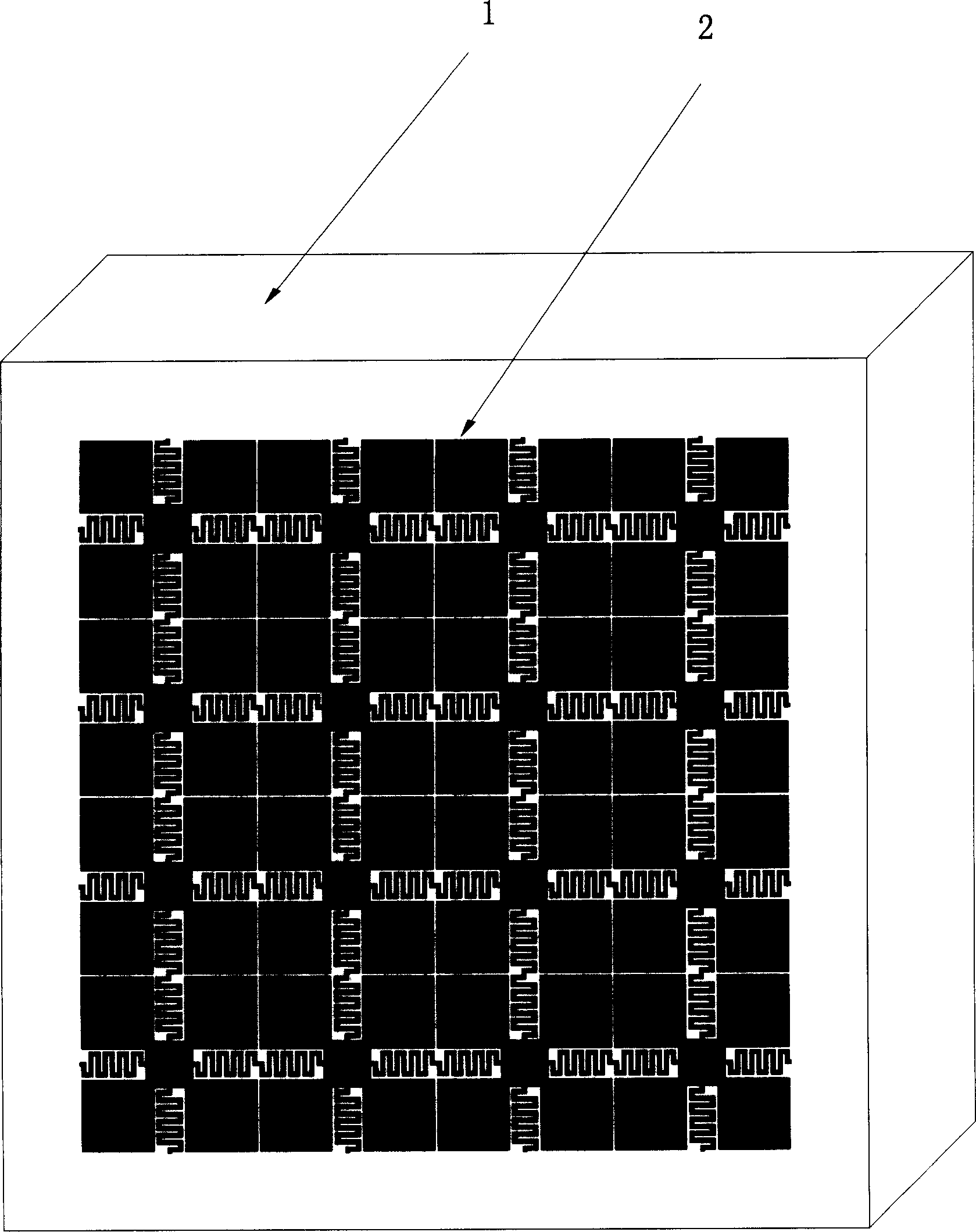
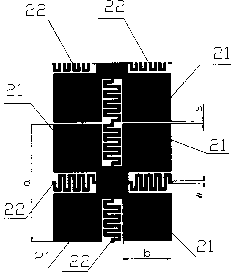
[0024] Such as figure 1 Shown, a kind of application method of high-dielectric microwave composite functional material on the antenna, described high-dielectric microwave composite functional material adopts component to be Sr 1-x Ba x TiO 3 High dielectric microwave ceramic materials. Using the high-dielectric microwave ceramic material as the medium, a periodic electromagnetic bandgap structure is formed on the surface of the medium by standard photolithography process or chemical plating method. The electromagnetic bandgap structure in the figure can be made of metal copper, silver, aluminum or gold. . Such as figure 2 As shown, the electromagnetic band gap structure 2 is a planar structure composed of a plurality of square unit cells, and the unit cell is composed of two curved wires 22 perpendicular to each other arranged in the middle of the unit cell and four wires separated by the wires 22. The conductive block 21 is composed of the conductive block 21, and the c...

Embodiment 2

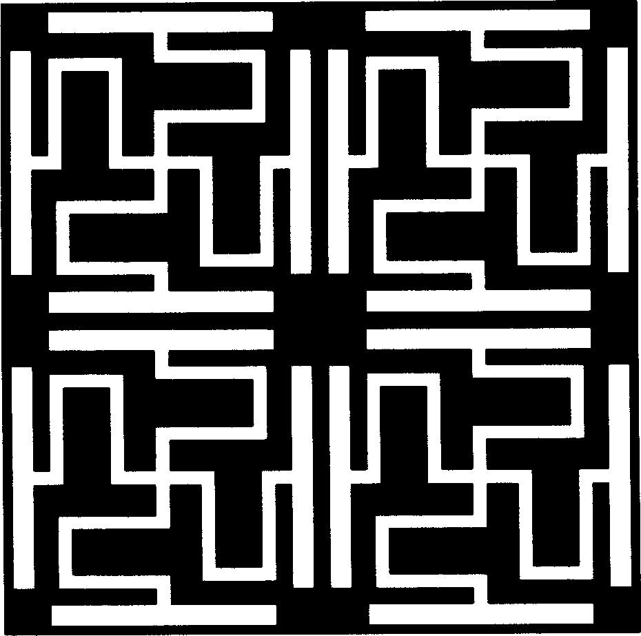
[0030] Such as image 3 As shown, the electromagnetic bandgap structure is a planar structure composed of a plurality of square unit cells, and the edge of the unit cell is provided with four blank bars parallel to the four sides of the unit cell, and the middle part of the unit cell is provided with two vertical bars parallel to each other. A period of interconnected square waveform blank strips, the two ends of each blank strip communicate with the middle parts of the two blank strips, and the part of the unit cell structure except the blank strips and the blank strips is a conductive block.

Embodiment 3

[0032] Such as Figure 4 As shown, the electromagnetic bandgap structure is a planar structure composed of a plurality of square unit cells, the edge of the unit cell is provided with four conductive strips parallel to the four sides of the unit cell, and the middle part of the unit cell is provided with two mutually perpendicular and parallel A period of interconnected square-wave conductive strips, the two ends of each conductive strip communicate with the middle of the two conductive strips.


PUM


Abstract

The invention discloses an antenna of high-dielectric microwave composite function, which is characterized by the following: the material adopts Sr1-xBaxTiO3(X=0.05-0.95) high-dielectric microwave ceramic material with surface containing periodical electromagnetic band-gap structure, which can be antenna base material as well as radiation dielectrics; this new method minimizes the bulk, which guarantees radiation efficiency and benefit for GPS(f=1.575GHz),2G PCS(f=1.8GHz),3G PCS(f=1.7-2.1GHz),802.11Blue Tooth communication (f=2.4-2.5GHz) and 802.16 WIMAX(f=3.4-3.53GHz) wireless communication domain.

Description

technical field [0001] The invention relates to an application method of a high-dielectric microwave composite functional material on an antenna, in particular to a method composed of Sr 1-x Ba x TiO 3 (X=0.05~0.95) application method of the high dielectric microwave ceramic material on the antenna. Background technique [0002] With the rapid development of communication technology, the requirements for miniaturization and integration of communication devices are increasing day by day. Microwave ceramic materials with high dielectric constant, high thermal stability, and low loss can meet the requirements of miniaturization and integration of communication components, and are widely used in various communication components. Electromagnetic Bandgap (EBG), also known as Phototic Bandgap (PBG) or photonic crystal, is a new concept and new material proposed in the late 1980s. It is composed of different A new type of composite functional material formed by periodically arra...

Claims


Application Information

Patent Timeline
IPC IPC(8): H01Q1/00H01P1/20H01Q1/38H01Q13/00
CPCH01P1/2005
Inventor 贺连星刘晓晗殷杰羿丁振宇资剑李毅
Owner 上海联能科技有限公司
Why Eureka
Try Eureka