
Rear monitoring device of engineering machinery

A technology of construction machinery and monitoring devices, which is applied in the direction of earth movers/excavators, construction, etc., and can solve problems such as impractical and difficult

Active Publication Date: 2011-07-27
NIHON KENKI CO LTD
View PDF1 Cites 0 Cited by
  • Summary
  • Abstract
  • Description
  • Claims
  • Application Information

AI Technical Summary

Problems solved by technology

This operation is very difficult and has impractical problems

Method used


Image

  • Rear monitoring device of engineering machinery
  • Rear monitoring device of engineering machinery
  • Rear monitoring device of engineering machinery

Examples


Embodiment Construction

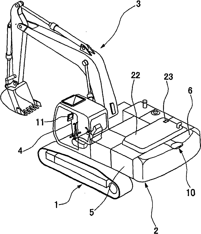
[0047] Next, specific embodiments of the present invention will be described with reference to the drawings. first, figure 1 The overall structure of a hydraulic excavator as an example of a construction machine. In the figure, 1 is an undercarriage, and 2 is an upper revolving body rotatably provided on this undercarriage 1. As shown in FIG. A working mechanism 3 for performing operations such as excavation is attached to the upper revolving body, and a cab 4 is provided in parallel with the working mechanism 3 . A machine room case 5 is provided at the rear of the cab 4 , and a balance weight 6 is provided at the rear of the machine room case 5 .

[0048] From figure 1It can be clearly seen that, with this hydraulic excavator, it is not possible to obtain a viewing area to the rear from the cab 4 . For this reason, for example, in order to ensure the safety of the vehicle when it is backing up, a rear monitoring device is provided that assists the operator in obtaining a...


PUM


Abstract

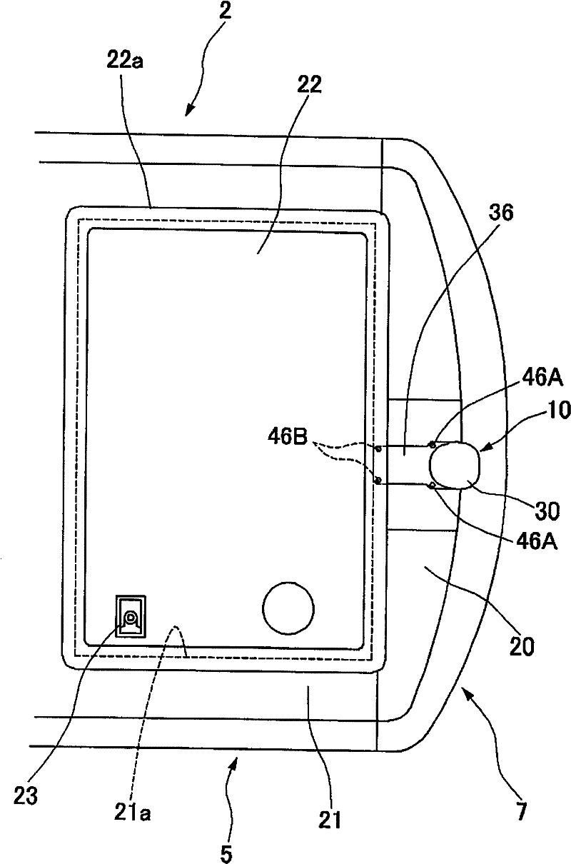
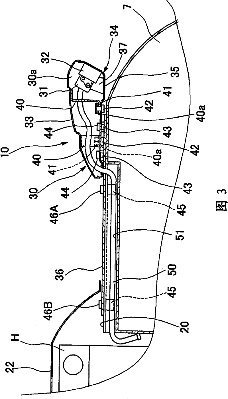
The invention provides a camera device for back supervision, which is anti-theft without extra processing mechanical box or balancing additional weight shell. The camera (31) is mounted on holding seat (32), holding seat is installed on bottom main body (35), said main body is connected to mounting plate (36) through nut (44), cover unit (33) is matched onto the bottom main body and is connected through screwing bolt (42) into nut (41) from lower side surface of main body, and it is not necessary to draw out camera from camera shell (30), fixing mounting plate through bolt (46A) (46B) to surface part (20) of shell, and the bolt (46B) is inside the generator cover (22). When the generator cover (22) is locked by a lock (23), the camera unit (10) can not be separated from surface part (20) of the balance additional weight shell (6).

Description

technical field [0001] The present invention relates to a rear monitoring device on construction machinery, which is installed on the upper rotating body of construction machinery such as a hydraulic excavator, and is used to ensure a rear observation area that cannot be seen from the cab. Background technique [0002] As a construction machine, such as a hydraulic excavator, there is an operating mechanism provided on the upper rotating body. The upper rotating body is installed on the lower traveling body with an automatic propulsion mechanism through a rotating device. By operating the operating mechanism, it can Carry out excavation and other operations on sandy soil. In order to make the lower traveling body drive the vehicle to travel, the rotation of the upper rotating body and the action of the working mechanism, a cab is arranged on the upper rotating body. A driver's seat on which an operator sits is provided in the cab, and operating mechanisms such as operating ...

Claims


Application Information

Patent Timeline
Patent Type & Authority Patents(China)
IPC IPC(8): E02F9/24
CPCE02F9/261E02F9/0858
Inventor 矶部浩之平贺正纪立山胜好
Owner NIHON KENKI CO LTD
Learn More