
Stapler

A stapler and staple technology, which is applied in the direction of nailing staple tools, nailing tools, manufacturing tools, etc., can solve the problem that the bending shape of the staple foot cannot be maintained stably, and the length of the movable clamp cannot be greatly formed. , poor cutting, etc.

Inactive Publication Date: 2010-05-26
MAX CO LTD
View PDF10 Cites 0 Cited by
  • Summary
  • Abstract
  • Description
  • Claims
  • Application Information

AI Technical Summary

Problems solved by technology

However, in this binding method, there are following problems: it is necessary to form a guide structure for guiding the legs of the staples on the clincher mechanism, so that the sides of the legs of the staples are adjacent to each other, high dimensional accuracy is required when mounting parts, and the cost is high. Becomes high
Therefore, due to the accumulation of dimensional tolerances of components such as the drive rod and the drive cam, etc., the swing stroke amount of the front end of the drive rod changes, or when the range of the operating stroke deviates, there is a problem that the movement of the drive rod is tight. The action stroke of the pliers changes, the final action position of the clamp surface of the movable pliers is not accommodated within the specified range, the staple legs float from the back of the binding paper or the front end of the staple legs protrudes to the binding paper surface side, so that the bent shape of the staple foot cannot maintain a stable state
[0008] And, in the staple leg cutting mechanism that cuts off the staple leg by the movable clincher and the fixed cutter as described in Japanese Patent Application Publication No. 02-021922, a pair of movable clinchers are respectively axially fixed, and are rotatably fixed. Support, in order to cut the staple foot between the movable cutting edge of the two movable pliers and the fixed cutting edge of the fixed cutter, the setting of the gap between the two cutting edges requires high dimensional accuracy, so There is a problem that the accuracy of parts dimensions, processing, and assembly is required, and the cost of parts and products increases, and there are problems such as poor cutting and bending failures due to wear and tear.
Since the direction of the burr formed on the end face of the staple leg cut by the above-mentioned two cutting edges is formed on the outer side of the staple leg, when the papers bound by the staple are stacked, there are Concern: Problems in quality such as burrs formed toward the side of the staple foot, scratches on overlapping paper, etc.
[0009] And, as described in the fair 03-025930, a movable cutting member is provided under the movable clincher, and by making the movable cutting member move in a direction substantially perpendicular to the penetrating direction of the staple leg, the fixed In the staple leg cutting mechanism that cuts the staple leg between the cutting parts, the movable clincher and the movable cutting part must be arranged on the same plane, so there is a gap between the movable clincher and the staple that cannot be formed large. The length of the portion where the foot snaps together so that the buckled shape of the staple foot cannot be bent into a stable shape
Since the direction of the burr formed when cutting the cut end of the staple leg is formed in the side direction of the staple, in the case of stacking the stapled paper, there is the following concern: Quality problems such as burrs formed toward the side of the staple foot, scratches on overlapping paper, etc.

Method used


Image

  • Stapler
  • Stapler
  • Stapler

Examples


Embodiment 1

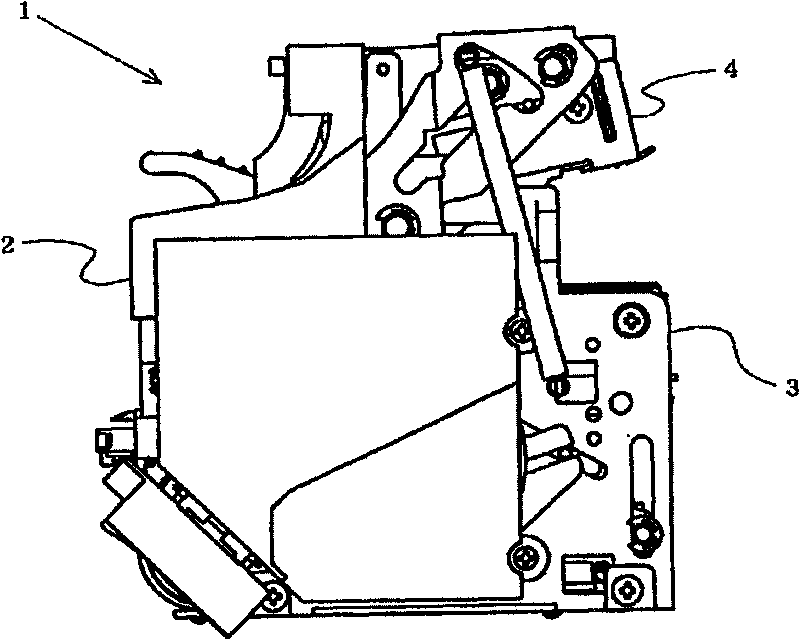
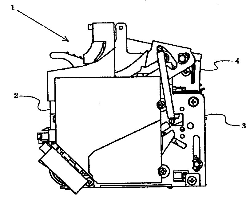
[0037] figure 1 A stapler showing an embodiment of the present invention. A motor and a driving mechanism for rotating and driving by the motor are accommodated in the machine frame 2 forming the outline of the stapler 1, and a drive-in mechanism part 3 is formed at the bottom of the machine frame 2, and the drive-in mechanism part 3. Driven by the above-mentioned driving mechanism, the staples formed in a U-shape are driven out to the binding paper. The driving mechanism part 3 of the stapler 1 of this embodiment forms a plurality of linear staple materials connected to each other into a U-shaped staple by a forming device, and the formed staple is formed by a driving device. The paper is driven upward toward the binding paper arranged above the driving mechanism unit 3 .

[0038] Furthermore, a clincher mechanism part 4 is formed on the upper part of the machine frame 2 opposite to the above-mentioned driving mechanism part 3, and the clincher mechanism part 4 makes the st...


PUM


Abstract

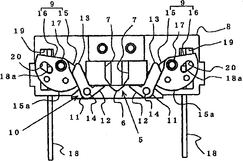
A staple leg cutting mechanism 5 is composed of a fixed cutter 6 interposed between staple legs S1 penetrated through binding sheets and a pair of movable cutters 7 disposed movable from the outside of the staple legs S1 to the inside thereof, and a clincher mechanism 10 is composed of a pair of movable clinchers 11 respectively disposed on the lower surface side of their associated movable cutters 7, whereby the staple legs S1 penetrated through the binding sheets are formed in an inwardly curved manner by the movable clinchers 11 and are then guided into and between the movable cutters 7 andfixed cutter 6, the movable cutters 7 are moved from the outside of the staple legs S1 to the inside thereof to thereby cut the leading end portions of the staple legs S1, and the staple legs S1 arebent along the binding sheets by the movable clinchers 11.

Description

technical field [0001] The present invention relates to a stapler comprising a movable clincher mechanism and a staple leg cutting mechanism, the movable clincher mechanism drives out a U-shaped staple to the binding paper so that the staple penetrating to the back side of the binding paper The staple legs are bent along the back side of the binding paper; after the staple legs penetrating to the back side of the binding paper are cut off by the staple leg cutting mechanism according to the thickness of the binding paper, the staple legs are bent along the The back side of the binding paper is warped. Background technique [0002] In an electric stapler or the like that drives staples into binding papers and binds and binds multiple sheets of binding papers with the staples, a driver with a direction toward the binding papers is driven from the surface side of the binding papers with a driving mechanism. A pair of legs extending in the same direction form a U-shaped staple,...

Claims


Application Information

Patent Timeline
Patent Type & Authority Patents(China)
IPC IPC(8): B25C5/15B25C5/02B27F7/21
Inventor 岸和彦清水利夫樋口一雄
Owner MAX CO LTD
Learn More