Wiper control method

A device control and wiper technology, which is applied in transportation and packaging, vehicle cleaning, vehicle maintenance, etc., can solve problems such as damage to wiper arms, connecting rods, and motors, and achieve the effect of ensuring vision

Inactive Publication Date: 2007-03-28
MITSUBA CORP
View PDF1 Cites 5 Cited by
  • Summary
  • Abstract
  • Description
  • Claims
  • Application Information

AI Technical Summary

Problems solved by technology

However, when the sensor for the motor rotation pulse fails, if the wiper is barely operated, the wiper arm, connecting rod, motor, etc. may be damaged, and the wiper device must be stopped.

Method used


Image

  • Wiper control method
  • Wiper control method
  • Wiper control method

Examples


Embodiment 1

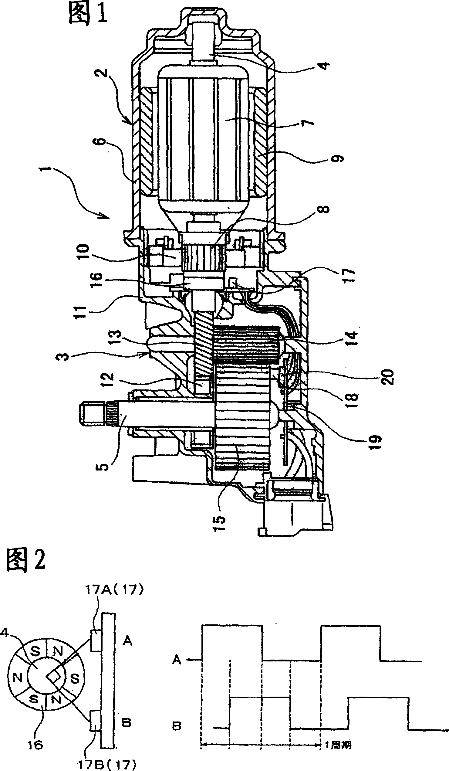
[0040] FIG. 1 illustrates the structure of a motor unit having a motor applicable to a method of controlling a wiper device according to Embodiment 1 of the present invention. The motor unit 1 of FIG. 1 is used as a drive source of a facing wiper device (opposed type) in which respective motors drive respective wiper arms (hereinafter simply referred to as arms) on the driver's seat side and the passenger's seat side. The arm in the motor unit 1 can change the direction of rotation when it reaches the up and down reverse position.

[0041] The motor unit 1 is composed of a motor 2 and a gear box 3 , the rotating shaft 4 of the motor 2 is decelerated in the gear box 3 and output to the output shaft 5 . The rotating shaft 4 freely rotates in a bottomed cylindrical yoke 6 through a bearing, and an armature core 7 wound with a coil and a commutator 8 are installed, and a plurality of permanent magnets are fixed on the inner surface of the yoke 6 . The commutator 8 is in sliding c...

Embodiment 2

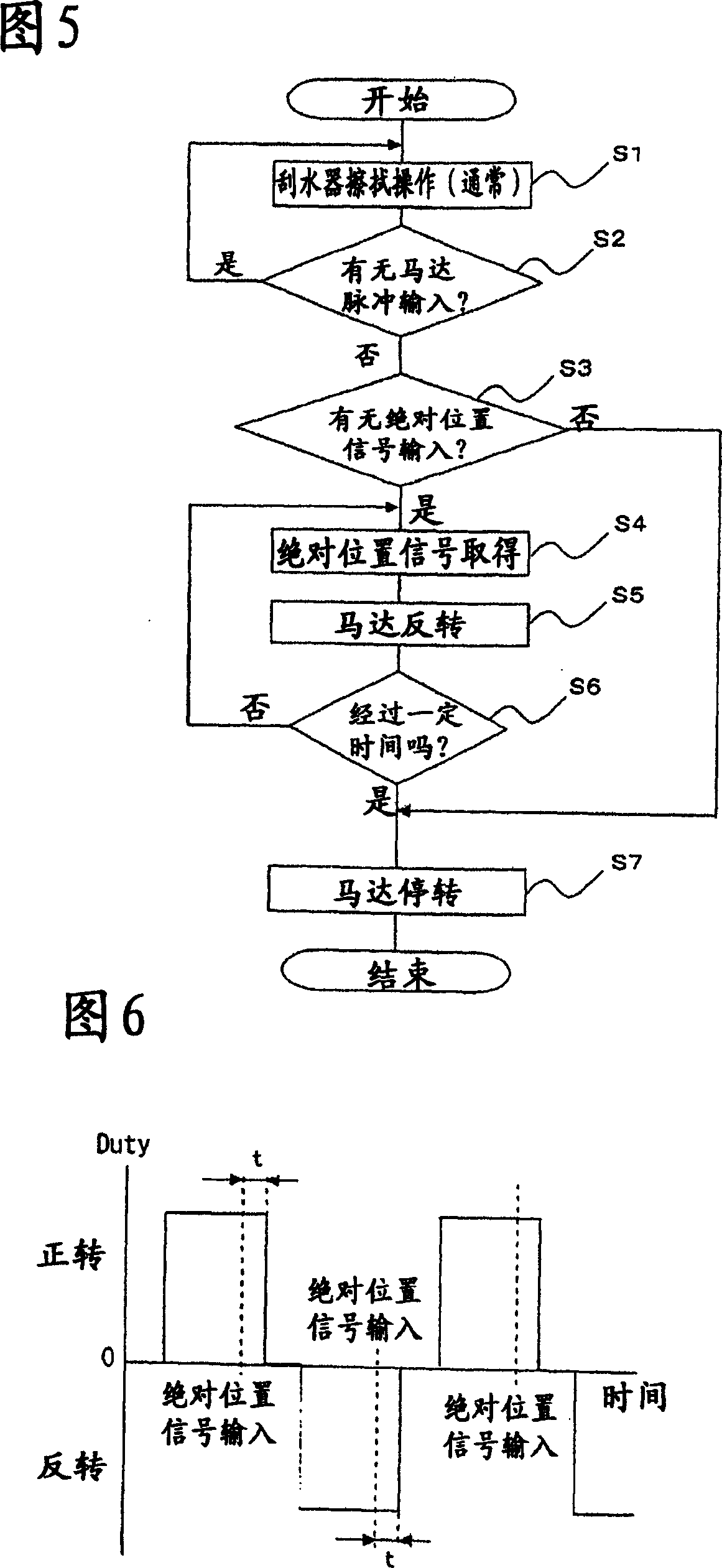
[0061] Next, the control method of the wiper device according to Embodiment 2 of the present invention will be described. FIG. 7 is a flow chart showing its processing steps. This control method is also the same as that of Embodiment 1, and is implemented in the motor unit 1 of FIG. 1 . In addition, in the following embodiments, the same components and parts as those in the first embodiment are given the same reference numerals and their descriptions are omitted.

[0062]In Embodiment 2, step S11 is a normal wiper control process, based on the absolute position signal and the position of the motor pulse detection arm, the forward and reverse rotation of the motor is controlled to perform the reverse wipe operation of the wiper blade. Same as the situation in Embodiment 1, while performing this normal control, monitor whether there is a motor pulse input in step 12, if there is a motor pulse input, then continue the normal control (S11), if there is no input, then proceed to S...

Embodiment 3

[0069] Now, the control method of the wiper device according to Embodiment 3 of the present invention will be described, and FIG. 9 is a flow chart showing its processing steps. In Embodiment 3, step 31 is a normal wiper control process, which detects the position of the arm through the absolute position signal and the motor pulse to perform the reverse wipe operation of the wiper blade, and executes the forward and reverse control of the motor. While carrying out this normal control, same as the situation of embodiment 1, monitor whether there is the input of motor pulse in step S32, can continue normal control (S31) when there is the input of motor pulse, and when there is no motor pulse 20 When it is input, it proceeds to step S33 and the following steps, and executes exception handling.

[0070] In step S33, regardless of the current rotation direction and position, no matter what the situation is, when the motor 2 is in the forward rotation direction (for example, the dir...


PUM


Abstract

To ensure visibility of the driver by continuing operation of a wiper even upon failure of a sensor for a motor rotation pulse. [MEANS FOR SOLVING PROBLEMS] A wiper arm is reciprocated for wiping by rotating a motor forward and reversely, and the operation of the wiper arm is controlled according to an absolute position signal outputted when the wiper arm exists at a predetermined position and a motor pulse outputted as the motor rotates. Input of the motor pulse is recognized (S32). When an abnormality occurs in the motor pulse, the motor is rotated forward for a predetermined time at a constant duty (S33). After a forward driving, the motor is rotated reversely for a predetermined time at a constant duty (S34). Consequently, the wiper arm continues reciprocal wiping operation even when a relative position signal is abnormal, thus ensuring visibility of the driver. Forward / reverse operation is continued for a predetermined time, and then the motor is stopped (S35, S36).

Description

technical field [0001] The present invention relates to a control method of a wiper device for a vehicle such as an automobile, in particular to a control method of a wiper device using a forward and reverse driven motor as a driving source. Background technique [0002] In recent years, in wiper devices for vehicles such as automobiles, with the narrowing of the installation space, the working area of ​​the link device between the motor and the wiper arm will be reduced to less than half. The system to drive the wiper arm is entering practical use. In this wiper system, when the wiper arm reaches the up-and-down reverse position, the rotation direction of the motor needs to be changed, so the position and speed of the wiper arm must be detected when controlling the motor. [0003] For example, in the system disclosed in Patent Document 1, the position and speed of the wiper arm are detected using motor rotation pulses generated in conjunction with the rotation of the motor...

Claims


Application Information

Patent Timeline
Patent Type & Authority Applications(China)
IPC IPC(8): B60S1/08
CPCB60S1/08
Inventor 池田健狩野雅巳
Owner MITSUBA CORP
Why Eureka
Try Eureka