Pallet box folding device and pallet box

A folding device and pallet box technology, applied in the directions of packaging, transportation and packaging, rigid containers, etc., can solve the problems of wasting storage space and high cost per box, and achieve the effect of making full use of storage space and reducing the protruding height.

Inactive Publication Date: 2007-04-25
CHINA INTERNATIONAL MARINE CONTAINERS (GROUP) CO LTD +1
View PDF2 Cites 0 Cited by
  • Summary
  • Abstract
  • Description
  • Claims
  • Application Information

AI Technical Summary

Problems solved by technology

[0004] Therefore, the above-mentioned existing pallet box not only has a higher cost per box, but also requires more stacking space when stacking without a load, which requires more storage space to be wasted to a certain extent

Method used


Image

  • Pallet box folding device and pallet box
  • Pallet box folding device and pallet box
  • Pallet box folding device and pallet box

Examples


Embodiment Construction

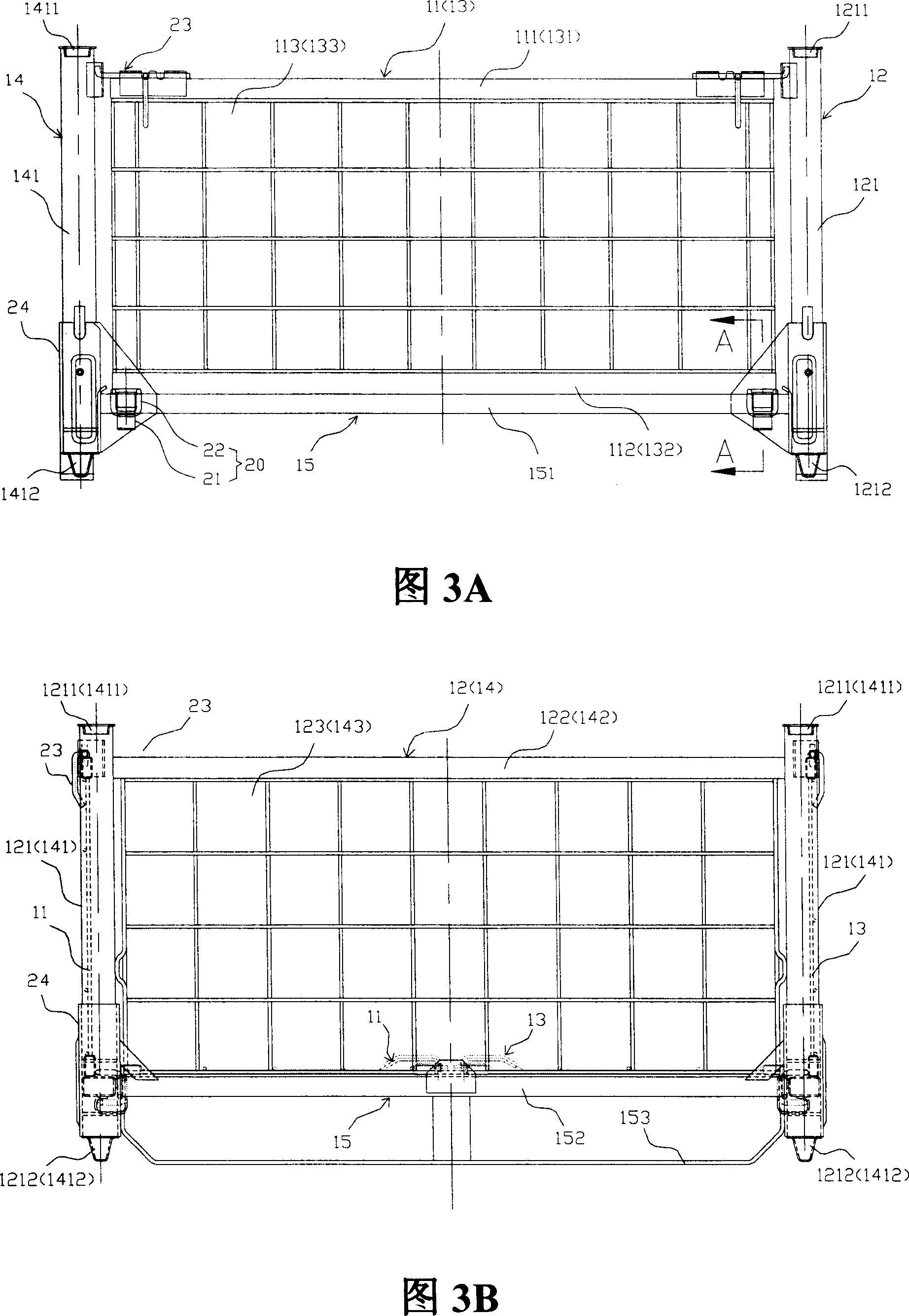
[0040] As shown in FIGS. 3A-3C , the pallet box of the present invention includes a bottom frame 15 , two side frames 11 , 13 , and two end frames 12 , 14 . Underframe 15 can be framed by underframe side beams 151 and underframe end beams 152, and some intermediate beams to strengthen the strength and support can be arranged in the frame, for the convenience of loading, a base plate can also be laid as a bearing plane 154 . The end frame 12 / 14 can be composed of end frame columns 121 / 141 on both sides, end frame upper beam 122 / 142 (end frame lower beam can also be set as required), end plate (network) 123 / 143 (according to different requirements, the end frame The plate is not limited to the structure of the plate body, and can also be a mesh structure. For the convenience of description, only the end plate structure is used as an example to illustrate). The angle upright column 24 of 15 corners and the connecting device (not marked among the figures) of connecting angle upri...


PUM


Abstract

The invention relates to a folder of support box and relative support box. Wherein, between the side frame / end frame and the bottom support of support box, the folder is connected and drives the side frame / end frame to be folded on the bottom support. Said folder comprises a limit sheath mounted at the inner side of side beam of bottom support, with a right-angle motion space, a connecting ring with right-angle section matched with the limit sheath to be sheathed into the motion space to connect the limit sheath and move in the space; one part of ring is fixed on the lower beam of side frame / end frame. The invention can reduce the cost.

Description

technical field [0001] The invention relates to a logistics appliance, in particular to a pallet box folding device and a pallet box using the folding device. Background technique [0002] As shown in Figures 1A and 1B, the Japanese patent application number is JP08-294979, and the publication number is 10-139040, which discloses a pallet box including a bottom frame, side frames and end frames. Among them, as shown in Figures 2A to 2D, the end frame is combined with the corner column of the bottom frame to complete the pairing, and the side frame 39 and the bottom frame are connected to the bottom frame through the side frame connecting ring 106 installed on the side frame lower beam 101. The limit sleeve 107 on the inner side of the frame side beam 53 cooperates to realize the connection with the bottom frame. The assembly between the side frame 39 and the end frame is realized by a lock. [0003] However, as shown in Figures 2A and 2B, in the prior art, the spacer sleev...

Claims


Application Information

Patent Timeline
Patent Type & Authority Applications(China)
IPC IPC(8): B65D19/38B65D19/06B65D21/02
CPCB65D19/18B65D2519/00502B65D2519/00661B65D2519/00094B65D2519/00233B65D2519/00532B65D2519/00059B65D2519/00905B65D2519/00512B65D2519/00268B65D2519/00562B65D2519/00164B65D2519/00024B65D2519/00646
Inventor 蔡立陈宝柱
Owner CHINA INTERNATIONAL MARINE CONTAINERS (GROUP) CO LTD
Why Eureka
Try Eureka