Processor arrangement

A processor, processor unit technology, used in instrumentation, computer control, control/regulation systems, etc.

Inactive Publication Date: 2007-05-09
INFINEON TECH AG
View PDF0 Cites 0 Cited by
  • Summary
  • Abstract
  • Description
  • Claims
  • Application Information

AI Technical Summary

Problems solved by technology

Furthermore, not only for cost reasons, these control and display functions are usually only implemented in very limited quantities

Method used


Image

  • Processor arrangement
  • Processor arrangement
  • Processor arrangement

Examples


Embodiment Construction

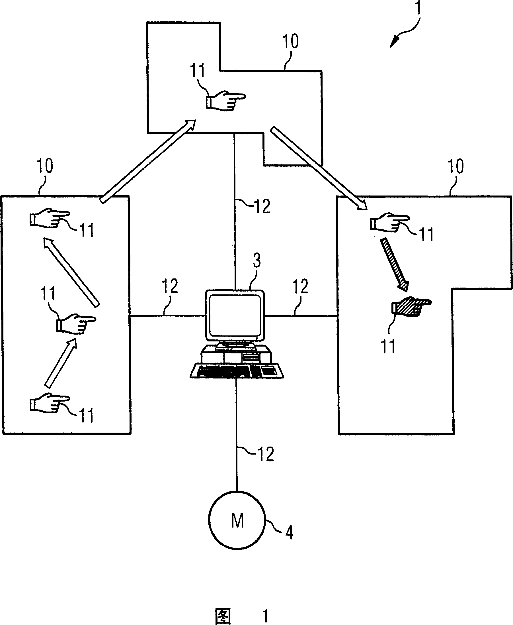
[0058] Figure 1 shows an exemplary embodiment of the invention.

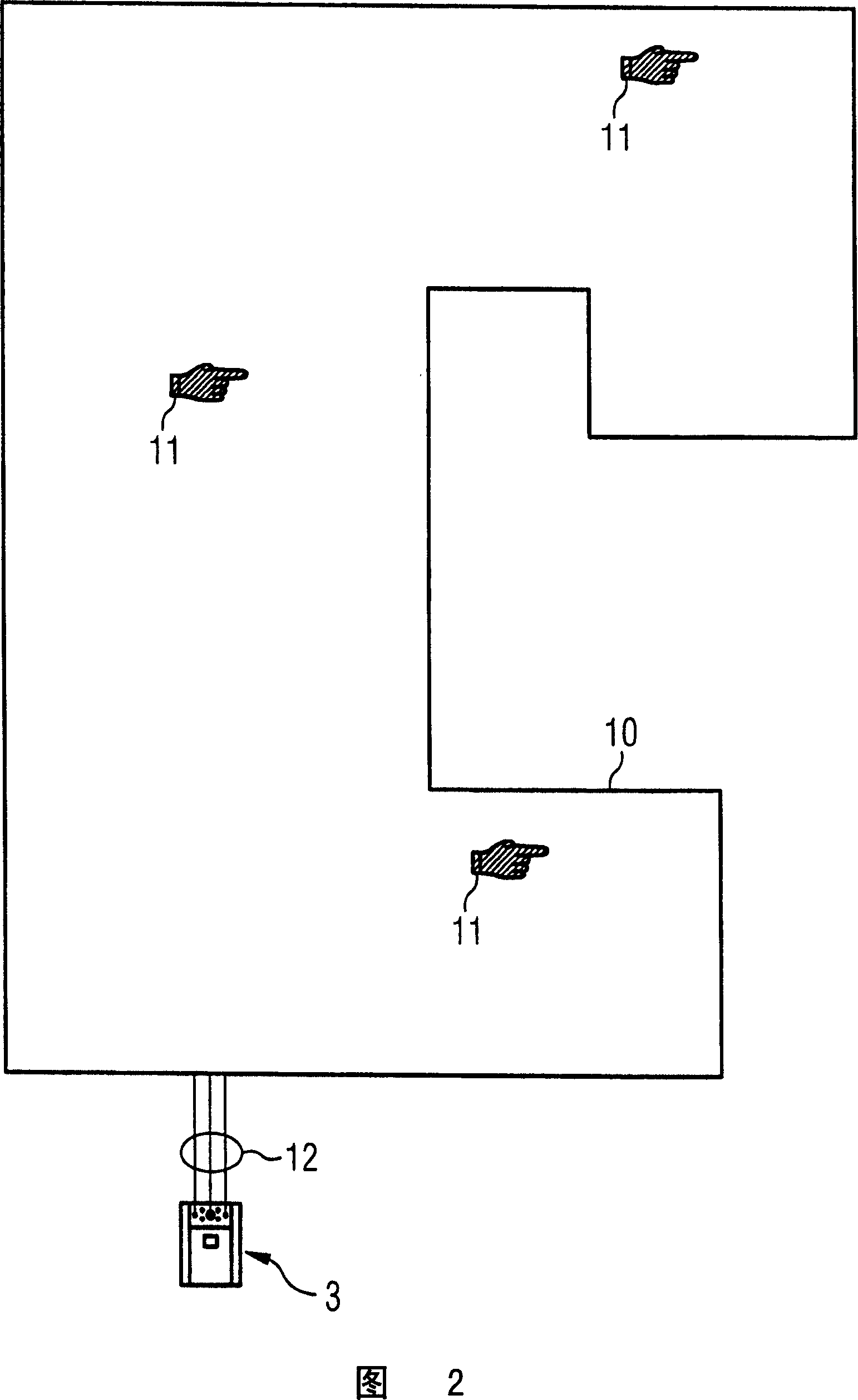
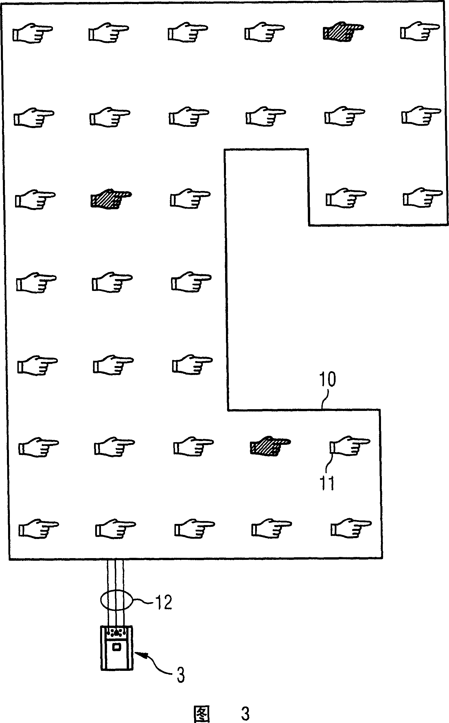
[0059] FIG. 1 shows by way of example how, in configuration mode, a virtual switch appearing on a fabric can be transformed across a network and also beyond network boundaries by passing the hand over said fabric. A subsequent touch at the location of the virtual switch activates the associated function. It depends on the implementation whether the position of the switch is marked, for example by means of a light-emitting diode, or whether the switch is visible.

[0060] This allows the desired control functions to be defined at any point within the network or group of connected networks. Functions can also occur in any number depending on preference and necessity, eg multiple identical light switches at specific but freely selectable points on a textile electronic wallpaper in a living room. In particular, said points can also be mainly limited to the vicinity of the user, e.g. in a vehicle by displacing the ...


PUM


Abstract

A processor arrangement having a plurality of processor units and a control computer. Each of the processor units is connected to at least one adjacent processor unit and has one control element and at least one communications interface for providing a data communications link with an adjacent processor unit. The control computer is connected to one of the processor units, and is configured for exchanging information with the processor unit and for assigning one control element of the plurality of control elements to a device that is electrically connected to the processor arrangement for the control of the device.

Description

technical field [0001] The invention relates to a processor device. Background technique [0002] It is desirable to flexibly implement control functions at variable locations in order to be able to operate electrical equipment with control functions arranged at these locations. [0003] Control elements for controlling technical equipment are usually located in fixed positions. Examples include, for example, window lift switches in vehicles, seat adjustment devices or speed displays, controls for appliances in domestic environments and consoles in industrial manufacturing. [0004] It is often desirable to be able to change the position of the control elements if another user uses the control elements, for example when the driver of the vehicle changes, or if operating requirements change, for example when reconfiguring a production system. [0005] To solve this problem, the following methods have been adopted so far, for example: [0006] Changes to save control and di...

Claims


Application Information

Patent Timeline
IPC IPC(8): G05B15/02
CPCG05B19/0421G05B2219/2206G05B2219/2224
Inventor T·斯图姆R·格拉塞C·劳特贝克A·斯托赫W·韦伯F·施利普
Owner INFINEON TECH AG
Why Eureka
Try Eureka