Illumination system

A lighting system and lighting equipment technology, applied in the field of lighting systems, can solve the problems of high cost and high investment cost, and achieve the effect of prolonging the maintenance period

Inactive Publication Date: 2007-05-09
ZUMTOBEL LIGHTING INC
View PDF0 Cites 3 Cited by
  • Summary
  • Abstract
  • Description
  • Claims
  • Application Information

AI Technical Summary

Problems solved by technology

[0004] On the one hand, the DALI-compliant light control systems described above work very satisfactorily and allow a very comfortable control of lighting installations, but on the other hand they require relatively high investment costs
E

Method used


Image

  • Illumination system
  • Illumination system
  • Illumination system

Examples


Embodiment Construction

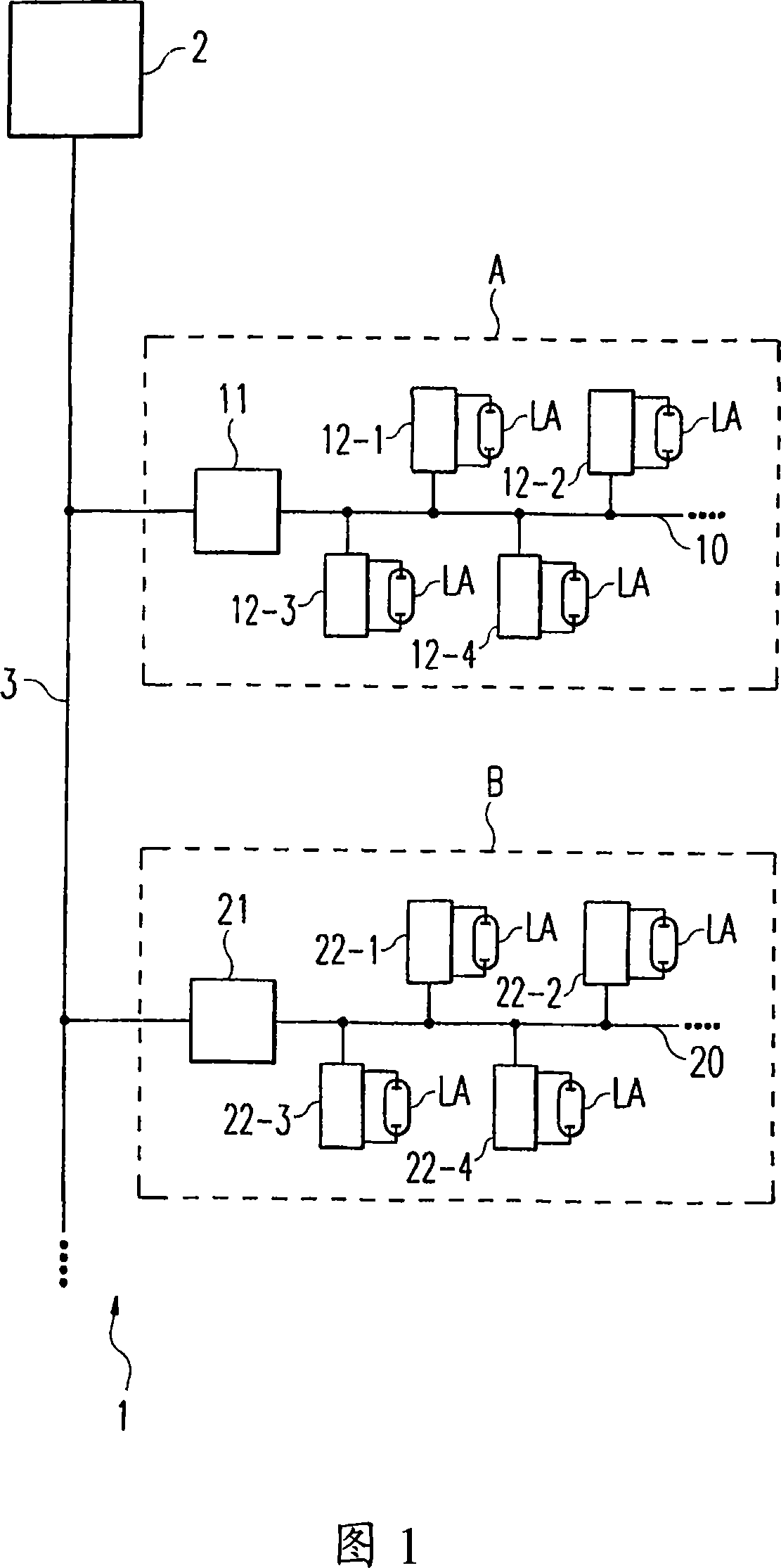
[0022] Figure 1 shows a lighting system, generally designated with reference numeral 1, which may be installed, for example, in larger office buildings or the like. The lighting system 1 is divided into a plurality of subsystems A and B, wherein each subsystem represents a lighting system according to the DALI standard. Each system A and B respectively has a local control unit 11 or 21, which is connected to the lighting control devices 12-1~12-4 or 22-1~22-4 through the corresponding line 10 or 20. Suitable lamps LA are connected to lamp operating devices by which the lamps are operated.

[0023] The two subsystems A and B are further connected via an additional bus 3 to a central control unit 2 which centrally manages the overall lighting system 1 . The bus 3 for connecting the subsystems A and B to the central control unit 2 is not a necessary line to make up a DALI system. Usually, it is more precisely other lines of a general building control system or the like.

[002...


PUM


Abstract

The invention relates to an illumination system (1) comprising a control unit (2), in addition to at least one decentralised lamp operation device (12, 22), which operates one or more allocated lamps (LA) and can be operated in different modes. According to the invention, the central control unit (2) and the lamp operation device (12, 22) are configured in such a way that the operating mode for the lamp operation device (12, 22) is selected and adjusted by or via the central control unit (2).

Description

technical field [0001] The invention relates to a lighting system with a control unit and at least one de-central lamp operating device for operating a lamp, wherein the lamp operating device can be operated in different operating modes. Background technique [0002] Lighting systems comprising multiple lighting fixtures interconnected by bus systems are often used in larger buildings. In each case, the lighting device is connected with a lamp operating device responsible for operating the connected lamps. Thus, a more complex system may control a plurality of individual light operating devices independent of the central station, for example in order to switch on and off connected lighting devices. [0003] In addition to the simple switch-on and switch-off functions, currently prevailing light control systems often also make it possible to set the brightness of the light, that is to say to dim the light. If such devices are incorporated into larger lighting systems, elect...

Claims


Application Information

Patent Timeline
IPC IPC(8): H05B37/02
CPCH05B37/0254H05B47/18
Inventor 甘特·约勒曼弗雷德·佩斯库拉特托马斯·罗斯
Owner ZUMTOBEL LIGHTING INC
Why Eureka
Try Eureka