Telescopic actuator with a main rod and an auxiliary rod, and method applying said actuator

A technology of auxiliary rods and actuators, which is applied in the directions of transmission, transportation and packaging, belts/chains/gears, etc., and can solve problems such as safety hazards

Active Publication Date: 2007-06-27
SAFRAN LANDING SYSTEMS
View PDF1 Cites 37 Cited by
  • Summary
  • Abstract
  • Description
  • Claims
  • Application Information

AI Technical Summary

Problems solved by technology

Specifically, in the application described above, the landing gear is c

Method used


Image

  • Telescopic actuator with a main rod and an auxiliary rod, and method applying said actuator
  • Telescopic actuator with a main rod and an auxiliary rod, and method applying said actuator
  • Telescopic actuator with a main rod and an auxiliary rod, and method applying said actuator

Examples


Embodiment Construction

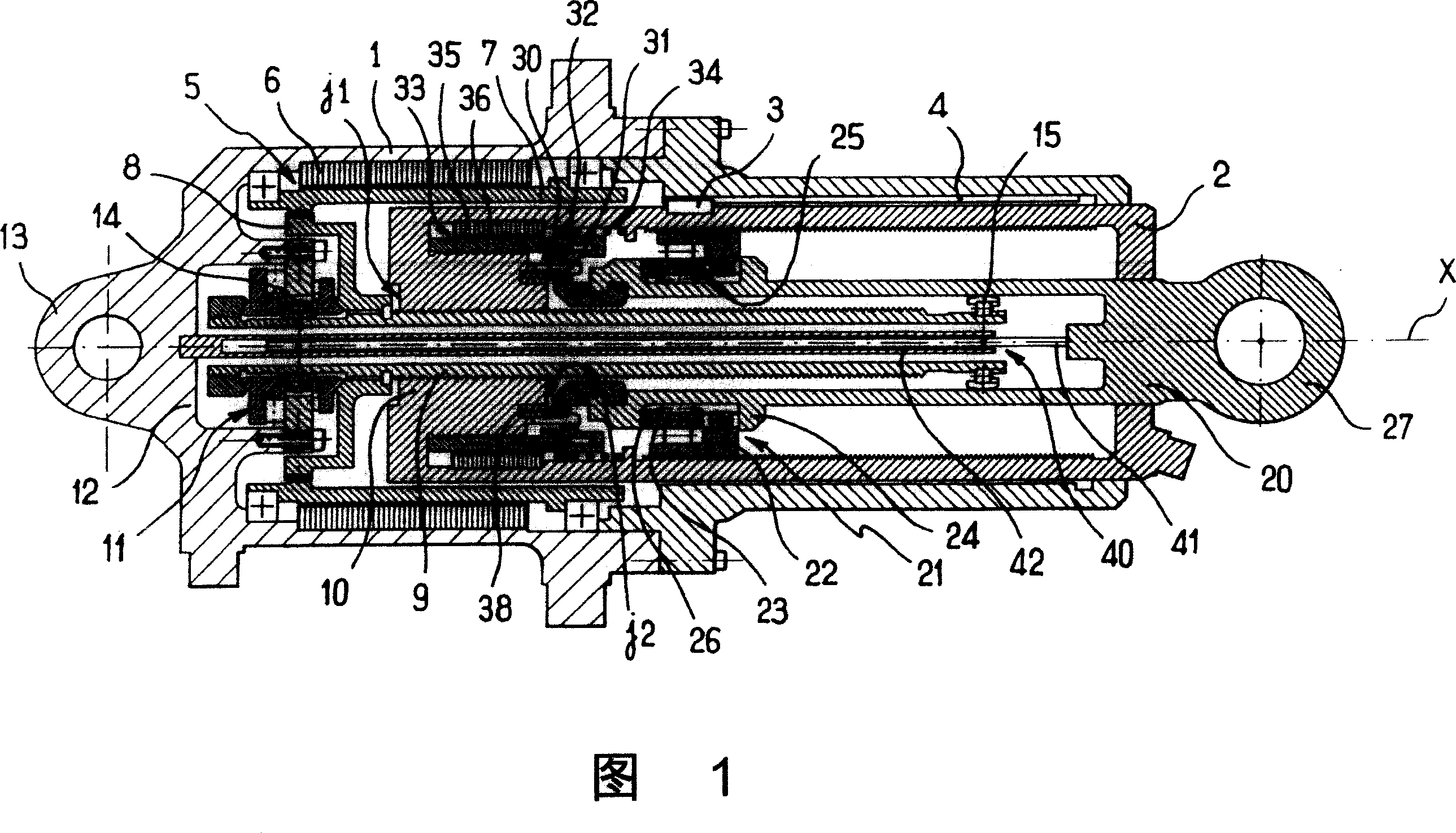
[0020] Referring to FIG. 1 , in a particular embodiment of the invention, the actuator comprises a barrel 1 forming a cylindrical interior closed by an end wall 12 with a lug 13 . A main rod 2 is mounted in the cavity for sliding along a sliding axis X and protrudes from the cylinder 1 to a greater or lesser extent through the open end of the cylinder constituting a bearing.

[0021] The actuator comprises control means for controlling the sliding of the main rod 2 relative to the cylinder 1 . The slide controls include:

[0022] - a key 3, fixed to the main rod 2 and cooperating with a groove 4 formed in the wall of the inner cavity of the cylinder 1, to prevent the rotation of the main rod 2 relative to the cylinder 1;

[0023] - a drive motor 5 comprising a stator 6 mounted stationary in the cylinder 1, and a rotor 7 mounted in the cylinder 1 in rotation about the axis X;

[0024] - A lead screw 9 extending along the axis X, mounted for rotation about the axis X in the cy...


PUM


Abstract

The invention relates to a telescopic actuator comprising a cylinder in which a main rod is mounted to slide telescopically along a sliding axis between a retracted position and an extended position. The actuator includes an auxiliary rod mounted to slide telescopically in the main rod along said sliding axis between a retracted position and an extended position, the actuator including controlled retaining means for retaining the auxiliary rod in the retracted position inside the main rod.

Description

technical field [0001] The present invention relates to an actuator having a primary rod and a secondary rod, and to methods of use thereof. Background technique [0002] Telescopic actuators of the cylindrical type are known comprising a cylinder in which a main rod is mounted for sliding along a sliding axis between a retracted position and an extended position. [0003] For example, such an actuator is used to deploy the landing gear of an aircraft. There is a very small risk (very small) that the main rod becomes clamped inside the cylinder, thus preventing not only the actuator from performing its function, but also the movement of the mechanical system into which the actuator is inserted. In particular, in the application described above, the landing gear becomes jammed and can no longer be deployed, which constitutes a safety hazard. [0004] In other fields, telescoping actuators are known comprising an auxiliary rod mounted slidably within the main rod along said ...

Claims


Application Information

Patent Timeline
IPC IPC(8): B64C25/00B64C25/10B64C25/18B64C25/20
CPCF16H25/205F16H2025/2059
Inventor D·布切顿H·查卢尔
Owner SAFRAN LANDING SYSTEMS
Why Eureka
Try Eureka