
Imaging device and display method for the same

An imaging device and imaging technology, applied in image communication, static indicators, cathode ray tube indicators, etc., can solve the problems of invisibility, reduced visibility, blocking, etc., so as to prevent the reduction of visibility and prevent possible The effect of reducing vision

Inactive Publication Date: 2011-10-12
SONY GRP CORP
View PDF5 Cites 0 Cited by
  • Summary
  • Abstract
  • Description
  • Claims
  • Application Information

AI Technical Summary

Problems solved by technology

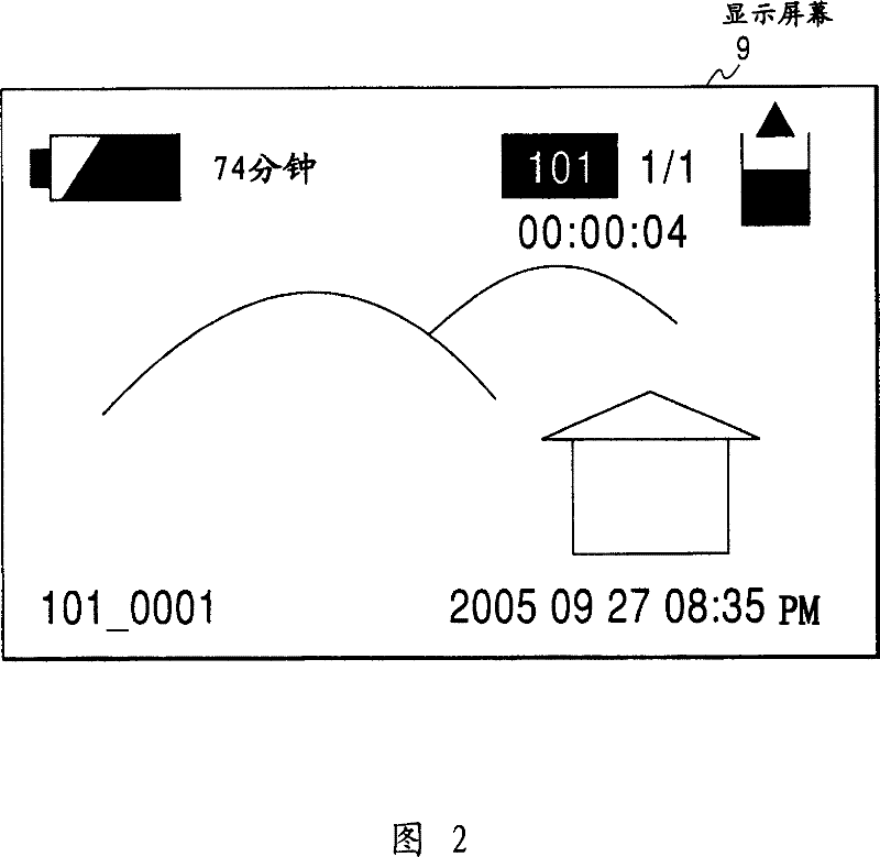
[0006] However, in terms of the displayed imaging results, an inherently darkly displayed object becomes less visible due to the bright on-screen display, undesirably resulting in reduced visibility
In this case, some monitors may prevent the user from seeing the details of the object
Also, when imaging dark objects in dark environments, users may be annoyed by glare from the on-screen display
Especially in recent years, imaging devices tend to display more on-screen display information, so the area of ​​on-screen display is correspondingly increased, resulting in significantly reduced visibility of such dark objects

Method used


Image

  • Imaging device and display method for the same
  • Imaging device and display method for the same
  • Imaging device and display method for the same

Examples


no. 1 example

[0022] (1) Configuration of the embodiment

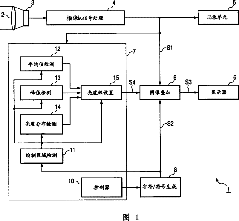
[0023] figure 1 is a block diagram depicting the configuration of a video camcorder according to an embodiment of the present invention. The video camcorder 1 has a mobile configuration powered by batteries. In video camcorder 1 , lens 2 focuses incident light, and forms an optical image of a subject on an imaging plane of imaging element 3 . The zoom magnification and the size of the aperture change in response to a user's operation.

[0024] The imaging element 3 photoelectrically processes an optical image of a subject formed on an imaging surface, and outputs an imaging result. The camera signal processing circuit 4 performs gamma correction, noise reduction, and other processing on the output signal from the imaging element 3, and outputs a video signal S1 formed of a luminance signal and a color difference signal.

[0025] The recording unit 5 data-compresses the video signal S1 output from the camera signal processing cir...

no. 2 example

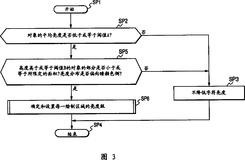
[0081] In the above embodiment, although a case has been described in which, after the brightness level displayed on the control screen is selected according to the average brightness level of one frame and the dynamics, finally the average brightness level of the display area on each screen and dynamic changes to determine the brightness level displayed on the control screen to control the brightness level accordingly, but the present invention is not limited thereto. For example, when sufficient characteristics can actually be ensured, the brightness level displayed on the control screen can be selected simply based on the average brightness level and dynamics of a frame to control the brightness level accordingly, or simply based on the The average brightness level and dynamics of the display area determine the brightness level displayed on the control screen to control the brightness level accordingly.

[0082] In the above embodiment, although a case has been described in...


PUM


Abstract

An image forming device which can display a monitor image of an imaging result captured by an imaging unit on a monitor and display the information about the device on the monitor in a way of displaying monitor image on the screen. The device includes a brightness grade detecting unit for detecting the brightness grade for the imaging result and outputting the brightness grade detecting result; and a display control unit for controlling the brightness grade based on the brightness grade detecting result to respond to the reduction of the brightness grade of the imaging result and reduce the displayed brightness grade for the information about the device.

Description

technical field [0001] The present invention relates to an imaging device and a display method for the imaging device, which can be applied to, for example, video cameras. The present invention prevents a reduction in visibility due to the on-screen display when imaging and displaying a dark object by reducing the brightness level of an on-screen display portion in response to a reduction in the brightness level of a monitor image . Background technique [0002] An imaging device of the related art, such as a video camcorder, has a monitor such as a liquid crystal display for displaying imaging results to allow a user to image a desired subject while monitoring the imaging results. The monitor also displays information such as the remaining recordable time of the recording medium on the display screen, so that the user can monitor imaging results while monitoring imaging-related conditions on the monitor. [0003] In the imaging device of the related art, for example, the ...

Claims


Application Information

Patent Timeline
Patent Type & Authority Patents(China)
IPC IPC(8): H04N5/57H04N5/445H04N5/225H04N5/92G09G5/10
CPCG09G5/377G09G2320/0626G09G2340/125G09G2340/14G09G2360/16H04N5/44504H04N5/57H04N5/772H04N5/781H04N5/85H04N5/907H04N23/634
Inventor 荷方谦二
Owner SONY GRP CORP
Learn More