Loading plate for weighing systems of vehicles in motion and related constraint system

a technology of weighing system and loading plate, which is applied in the direction of weighing apparatus details, instruments, measurement devices, etc., can solve the problem of allowing an adequate modeling accuracy

Active Publication Date: 2018-08-14
IWIM SRL
View PDF8 Cites 2 Cited by
  • Summary
  • Abstract
  • Description
  • Claims
  • Application Information

AI Technical Summary

Benefits of technology

[0029]The main advantage of the present invention is that a loading plate for a WIM system realized according to the teachings of the present invention, and bound to the WIM system as described, fulfills the main purposes for which it has been conceived.
is that a loading plate for a WIM system realized according to the teachings of the present invention, and bound to the WIM system as described, fulfills the main purposes for which it has been conceived.

Problems solved by technology

Typically, in the prior art systems, it is necessary to firmly fasten the weighing plate to the ground where the vehicles to be weighed pass, but said loading plates are normally placed in a manner that does not allow an adequate accuracy of modeling.

Method used


Image

  • Loading plate for weighing systems of vehicles in motion and related constraint system
  • Loading plate for weighing systems of vehicles in motion and related constraint system
  • Loading plate for weighing systems of vehicles in motion and related constraint system

Examples


Embodiment Construction

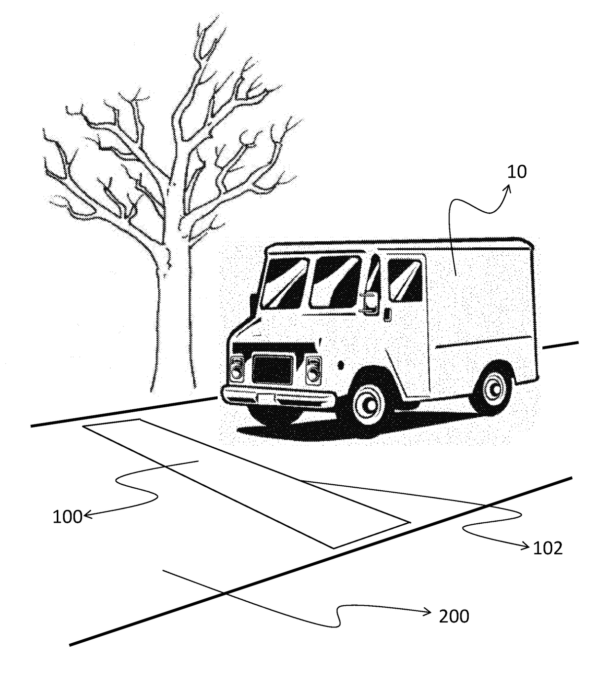
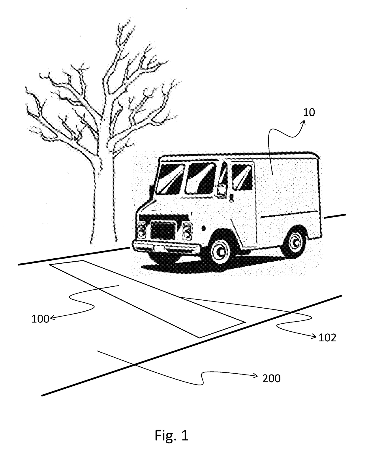
[0036]In FIG. 1 a scene that allows to understand how WIM system operatively works is represented. Under number 10 a vehicle that is moving in a street is shown. With the number 200 is represented the road surface that, for the good operation of the WIM system, should be as uniform and horizontal as possible. The number 100 indicates the WIM system, which occupies a strip placed transversely across the route so that the vehicles pass over it with all their wheels. As can be seen also in the scene of FIG. 1, the WIM system 100 forms a continuous plane with the roadway 200, and the vehicle 10, passing above, must not sense unevenness or steps. Again, FIG. 1 shows as the vehicle 10 accesses the area occupied by the WIM system 100 crossing a long side of the upper surface of said WIM system 100: the number 102 indicates an access side of said WIM system 100.

[0037]The WIM systems 100 according to the invention can be optimized both for making measurements of weight of vehicles transiting...


PUM


Abstract

The field of application of present invention relates to weighing systems of vehicles in motion also called WIM systems (Weigh In Motion).The indicated WIM system foresees the placement of a metal plate to the street level, above which vehicles to be weighed may transit, and this metal plate, which is also called loading plate, is mounted above a cavity obtained on the road surface so that it can flex at the passage of the vehicles above it.The system provides that the measurement of the deflection of said loading plate is carried out with the aid of suitable sensors, and that the estimated weight is obtained through the modeling of the flexing of said loading plate depending on the weight of the vehicle passing over.The invention discloses a particularly advantage configuration to achieve a weighing system that can be modelled with the required accuracy.

Description

BACKGROUND OF THE INVENTION[0001]1. Field of the Invention[0002]The field of application of present invention relates to weighing systems of vehicles in motion also called “WIM systems” (Weigh In Motion).[0003]2. Brief Description of the Prior Art[0004]The weight of the vehicles is a very interesting piece of information in many applications and its knowledge is of great importance.[0005]The most common methods for the weighing of vehicles consist in a static weighing: the vehicle stands above a weighing scale, it is stationary, and the weighing scale, which dimensions are sufficiently large, provides a weight measure.[0006]It is clear that the static weighing procedures are processes that, although they can achieve high accuracy, they cannot be applied in all contexts in which it would be necessary to know the weight of a vehicle. The main limitations are in the slowness of the procedure and in the fact that the “cooperation” by the driver of the vehicle is necessary, since he must...

Claims


Application Information

Patent Timeline
Patent Type & Authority Patents(United States)
IPC IPC(8): G01G21/22G01G19/02
CPCG01G21/22G01G19/022G01G19/03G01G19/02
Inventor DEMOZZI, ANDREACAPONERO, MICHELE ARTURO
Owner IWIM SRL
Why Eureka
Try Eureka