Disposable bioreactors and methods for construction and use thereof

a bioreactor and dissolvable technology, applied in the field of bioreactors, can solve the problems of low organism growth density, time-consuming and labor-intensive process, and low yield of bioreactors

Active Publication Date: 2018-08-28
DISTEK
View PDF10 Cites 9 Cited by
  • Summary
  • Abstract
  • Description
  • Claims
  • Application Information

AI Technical Summary

Problems solved by technology

While this has been the method of choice for process development for the last half century, the problem with this method is that the process is very time- and labor-consuming.
This can result in a turnaround time of 1 to 3 days between runs.
However, a problem with this type of system is that the mixing action and oxygen transfer are limited, resulting in a low organism growth density relative to the design of a traditional agitator and sparger (a device that bubbles gas through the bioreactor) in a “stirred tank” bioreactor.
In addition, the different mixing motion and bag geometry in the medical-type bag bioreactor does not lend itself to be scaled up to larger production processes.
These limitations of the initial single-use bioreactor designs have led to the development of “stirred-tank” single-use bioreactor products.
However, the design does not lend itself to small vessel sizes (e.g., less than 50 L), because the size of the fittings in the bag and the number of fittings for a standard bioreactor exceed the allowable accessible surface area on the bag.
However, unlike a single-use bag system, the rigid plastic used in this design cannot be folded or reduced in size for storage or disposal.
This burdens the end user with a requirement for a large environmentally-controlled area within the user's facility for storage of future vessels, as well as increased disposal costs associated with such larger, non-compressible vessels.

Method used


Image

  • Disposable bioreactors and methods for construction and use thereof
  • Disposable bioreactors and methods for construction and use thereof
  • Disposable bioreactors and methods for construction and use thereof

Examples


Embodiment Construction

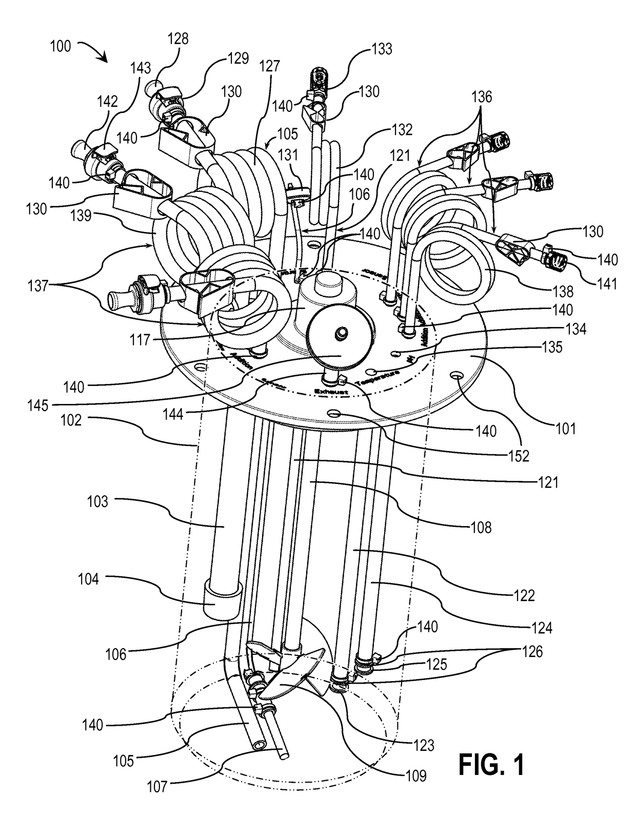
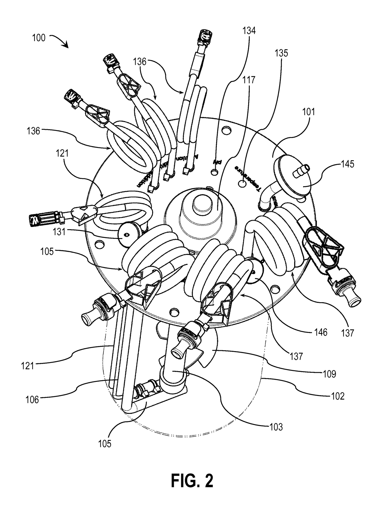
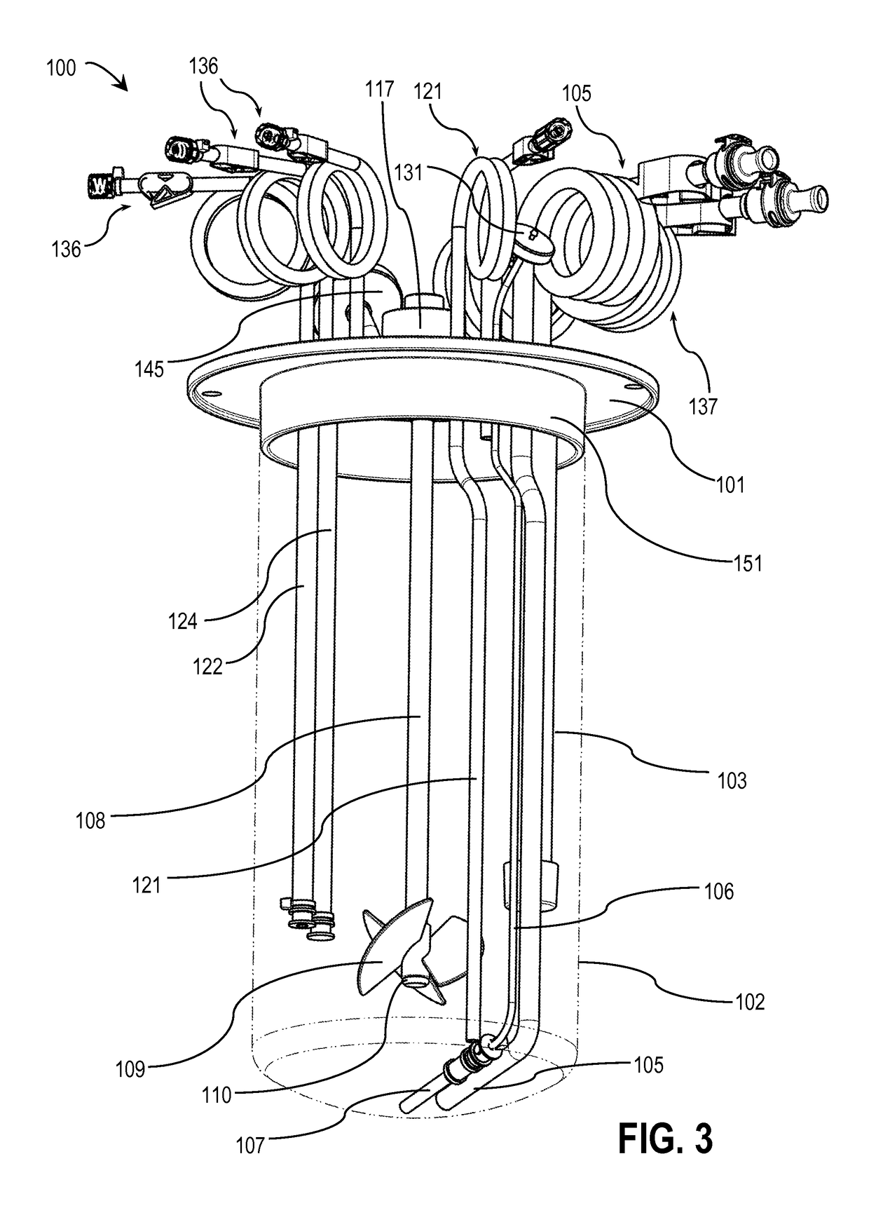
[0022]With reference to FIGS. 1-6, a disposable bioreactor 100 consistent with one embodiment of the invention is illustrated. The features described below are generally visible in FIG. 1, unless otherwise indicated.

[0023]Bioreactor 100 includes a circular headplate 101 that serves as a support for a vessel liner 102 (shown in broken lines). Vessel liner 102 is a flexible bag in which a culture medium is disposed, and in which organisms are grown in the culture medium. These organisms may be submerged (e.g., suspended or immobilized) in a liquid medium disposed within vessel liner 102, or attached to the surface of a solid medium disposed within vessel liner 102.

[0024]Headplate 101 also serves as a support for various additional components mounted on and through headplate 101. These additional components may vary in different embodiments of the invention. In this embodiment, the additional components include the following:

[0025]A dissolved oxygen (DO) sensor (not shown) is housed wi...


PUM

PropertyMeasurementUnit
turnaround timeaaaaaaaaaa
lengthaaaaaaaaaa
lengthaaaaaaaaaa

Abstract

In one embodiment, a disposable bioreactor including a headplate and a stirrer. The headplate has at least one inlet port aperture and one outlet port aperture formed therein and is adapted to couple sealingly with a bag capable of receiving a culture medium. The stirrer is coupled to and extends from the headplate and is adapted to stir the culture medium when the headplate is coupled to the bag. The bioreactor is adapted to fit within the upper opening of the stand of an existing conventional glass bioreactor, so that the bag is suspended within the vessel.

Description

FIELD OF THE INVENTION[0001]The present invention relates generally to the growth of biological cultures and, in particular, to bioreactors for biologically-active substances.BACKGROUND OF THE INVENTION[0002]A bioreactor is a vessel or container used for the growth of biological cultures, such as cells, bacteria, yeasts, or fungi. These cultures are used to produce a variety of biologically-active substances, including pharmaceuticals, fragrances, fuel, and the like.[0003]A conventional bioreactor vessel has a cylindrical shape and includes a mixing apparatus, means for introducing a gas supply, and a temperature control system. Most bioreactor applications require a sterilization process to ensure that the process run does not yield the growth of, or contamination from, undesirable biological organisms. Traditional methods of sterilizing bioreactors include the use of an autoclave (for smaller vessels) or a steam sterilization-in-place process (for larger vessels). In recent years,...

Claims


Application Information

Patent Timeline
Patent Type & Authority Patents(United States)
IPC IPC(8): C12M1/00C12M3/00C12M1/34C12M1/06C12N1/00
CPCC12M23/28C12M23/14C12M23/46C12N1/00C12M29/04C12M41/12C12M41/32C12M27/02C12M41/00
Inventor WATKINS, JEFFBRINKER, JEFFREY
Owner DISTEK
Why Eureka
Try Eureka