Membrane-seal assembly

a membrane and seal film technology, applied in the direction of fuel cells, cell components, electrochemical generators, etc., can solve the problems of significant waste of seal film material, achieve the effect of improving the performance and durability of mea, accelerating the commercialisation rate of fuel cells, and increasing market penetration

Active Publication Date: 2019-01-22
JOHNSON MATTHEY HYDROGEN TECH LTD
View PDF26 Cites 0 Cited by
  • Summary
  • Abstract
  • Description
  • Claims
  • Application Information

AI Technical Summary

Benefits of technology

[0011]To enable a faster rate of commercialisation of fuel cells and a greater market penetration it is necessary to make further improvements in the performance and durability of the MEA and also to reduce the materials usage and thus costs, and also to significantly reduce manufacturing costs and increase the manufacturing output rate for the MEA. As such continuous high volume manufacturing processes wherein a continuous roll of MEA is produced at high speed are being introduced as alternatives to manufacturing processes where single, individual MEAs are assembled from the separate MEA components. MEA designs are therefore required which simultaneously (i) improve the functional performance characteristics of the MEA, (ii) maximise the utilisation of the expensive materials and components, and (iii) are also capable of being manufactured by low cost, high speed and throughput manufacturing processes.
[0012]The present invention provides a design for a reinforced membrane-seal assembly, which provides for enhanced strength, mechanical stability and thus durability, a high utilisation of the ion-conducting membrane and the seal film material, and which is amenable to a high speed continuous manufacturing process.

Problems solved by technology

Thus a significant proportion of the seal film material is also wasted.

Method used


Image

  • Membrane-seal assembly
  • Membrane-seal assembly

Examples


Embodiment Construction

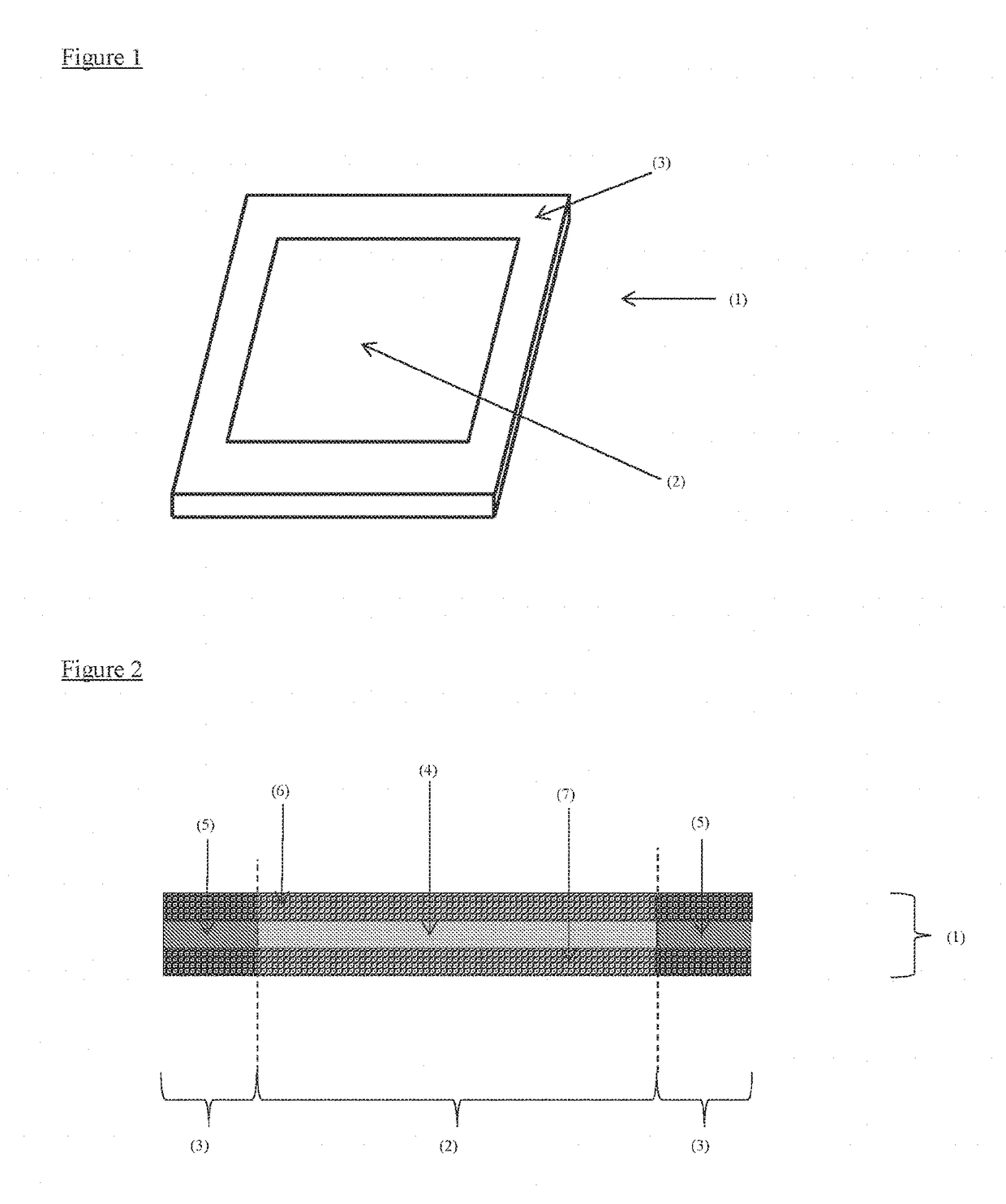
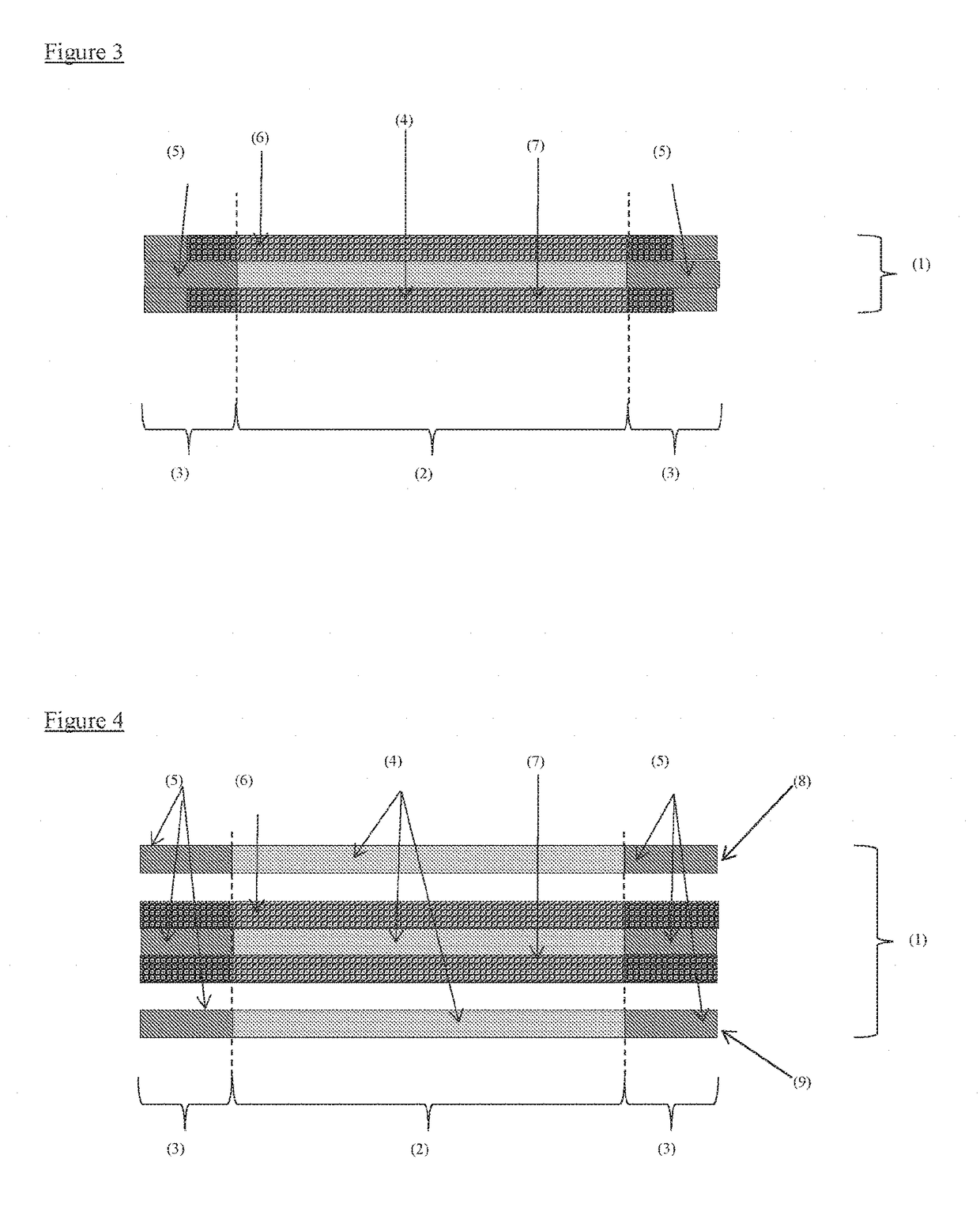
[0019]The present invention provides a reinforced membrane-seal assembly, the reinforced membrane seal assembly comprising an inner region and a border region and wherein the inner region comprises ion-conducting component and the border region comprises seal component;

[0020]wherein first and second planar reinforcing components each extend across the inner region into the border region and wherein the pores of each of the first and second planar reinforcing components in the inner region are impregnated with ion-conducting component and the pores of each of the first and second planar reinforcing components in the border region are impregnated with seal component.

[0021]One or more additional planar reinforcing components may extend across the inner region into the border region of the reinforced membrane-seal assembly.

[0022]Inner and Border Region

[0023]The inner region refers to a planar area in the x / y direction (in-plane direction) and which extends through the thickness of the r...


PUM

PropertyMeasurementUnit
porosityaaaaaaaaaa
porosityaaaaaaaaaa
porosityaaaaaaaaaa

Abstract

Disclosed is a reinforced membrane-seal assembly, the reinforced membrane-seal assembly including: an inner region and a border region and wherein the inner region includes ion-conducting component and the border region includes seal component; wherein first and second planar porous reinforcing components each extend across the inner region into the border region and wherein the pores of each of the first and second planar porous reinforcing components in the inner region are impregnated with ion-conducting component and the pores of each of the first and second planar porous reinforcing components in the border region are impregnated with seal component is disclosed. Also disclosed is a catalyst-coated reinforced membrane-seal assembly, a reinforced membrane-seal electrode assembly and an electrochemical device including the reinforced membrane-seal assembly.

Description

FIELD OF THE INVENTION[0001]The present invention relates to a reinforced membrane-seal assembly and in particular to a reinforced membrane-seal assembly having multiple reinforcing layers. The reinforced membrane-seal assembly of the invention is suitable for use in a fuel cell or an electrolyser.BACKGROUND OF THE INVENTION[0002]A fuel cell is an electrochemical cell comprising two electrodes separated by an electrolyte. A fuel, such as hydrogen or an alcohol, such as methanol or ethanol, is supplied to the anode and an oxidant, such as oxygen or air, is supplied to the cathode. Electrochemical reactions occur at the electrodes, and the chemical energy of the fuel and the oxidant is converted to electrical energy and heat. Electrocatalysts are used to promote the electrochemical oxidation of the fuel at the anode and the electrochemical reduction of oxygen at the cathode.[0003]In the hydrogen-fuelled or alcohol-fuelled proton exchange membrane fuel cells (PEMFC), the electrolyte is...

Claims


Application Information

Patent Timeline
Patent Type & Authority Patents(United States)
IPC IPC(8): H01M8/0276H01M8/1053H01M8/1041H01M4/92H01M8/0239H01M4/86H01M8/1058H01M8/1007H01M8/1004H01M8/1018
CPCH01M8/0276H01M4/8605H01M4/92H01M8/0239H01M8/1004H01M8/1041H01M8/1053H01M8/1058H01M8/1007H01M2300/0082H01M2008/1095Y02E60/50
Inventor BARNWELL, DAVID EDWARDCOLEMAN, ROBERT JEFFREYDICKINSON, ANGUSGRAY, PETER GEOFFREYSOARES, JORGE MANUEL CARAMELO
Owner JOHNSON MATTHEY HYDROGEN TECH LTD
Why Eureka
Try Eureka