Process of manufacturing a catalyst-coated membrane-seal assembly

a technology of catalyst coating and membrane sealing, which is applied in the direction of cell components, final product manufacturing, sustainable manufacturing/processing, etc., can solve the problems of premature failure, limited durability of fuel cell stacks, and intrinsic limitations of current manufacturing routes involving lamination of components in processes involving temperature and pressure, so as to reduce manufacturing costs and accelerate fuel cell commercialisation , the effect of increasing market penetration

Active Publication Date: 2017-04-13
JOHNSON MATTHEY HYDROGEN TECH LTD
View PDF0 Cites 5 Cited by
  • Summary
  • Abstract
  • Description
  • Claims
  • Application Information

AI Technical Summary

Benefits of technology

[0010]To enable a faster rate of commercialisation of fuel cells and a greater market penetration it is necessary to make further improvements to significantly reduce manufacturing costs and increase the manufacturing output rate for the MEA, whilst at the same time also improving the functional performance and durability of the MEA and also reducing the materials usage and thus costs. Current manufacturing routes that involve lamination of the components in processes involving temperature and pressure are intrinsically limited in their rate of assembly to just a few linear metres per minute. Also, as a result of the lamination process the MEA materials, and in particular the ion-conducting membrane, can be weakened during the high pressure and / or pressure bonding step, which leads to limited durability of the fuel cell stacks and premature failure. As such manufacturing processes are required where MEAs can be produced by low cost processes involving a minimal number of complex process steps, and at high speeds with the capability of producing several tens of linear metres per minute, but also simultaneously can produce MEA constructions designed for improved performance and durability and maximum utilisation of the expensive materials and components.

Problems solved by technology

Current manufacturing routes that involve lamination of the components in processes involving temperature and pressure are intrinsically limited in their rate of assembly to just a few linear metres per minute.
Also, as a result of the lamination process the MEA materials, and in particular the ion-conducting membrane, can be weakened during the high pressure and / or pressure bonding step, which leads to limited durability of the fuel cell stacks and premature failure.

Method used


Image

  • Process of manufacturing a catalyst-coated membrane-seal assembly
  • Process of manufacturing a catalyst-coated membrane-seal assembly
  • Process of manufacturing a catalyst-coated membrane-seal assembly

Examples


Embodiment Construction

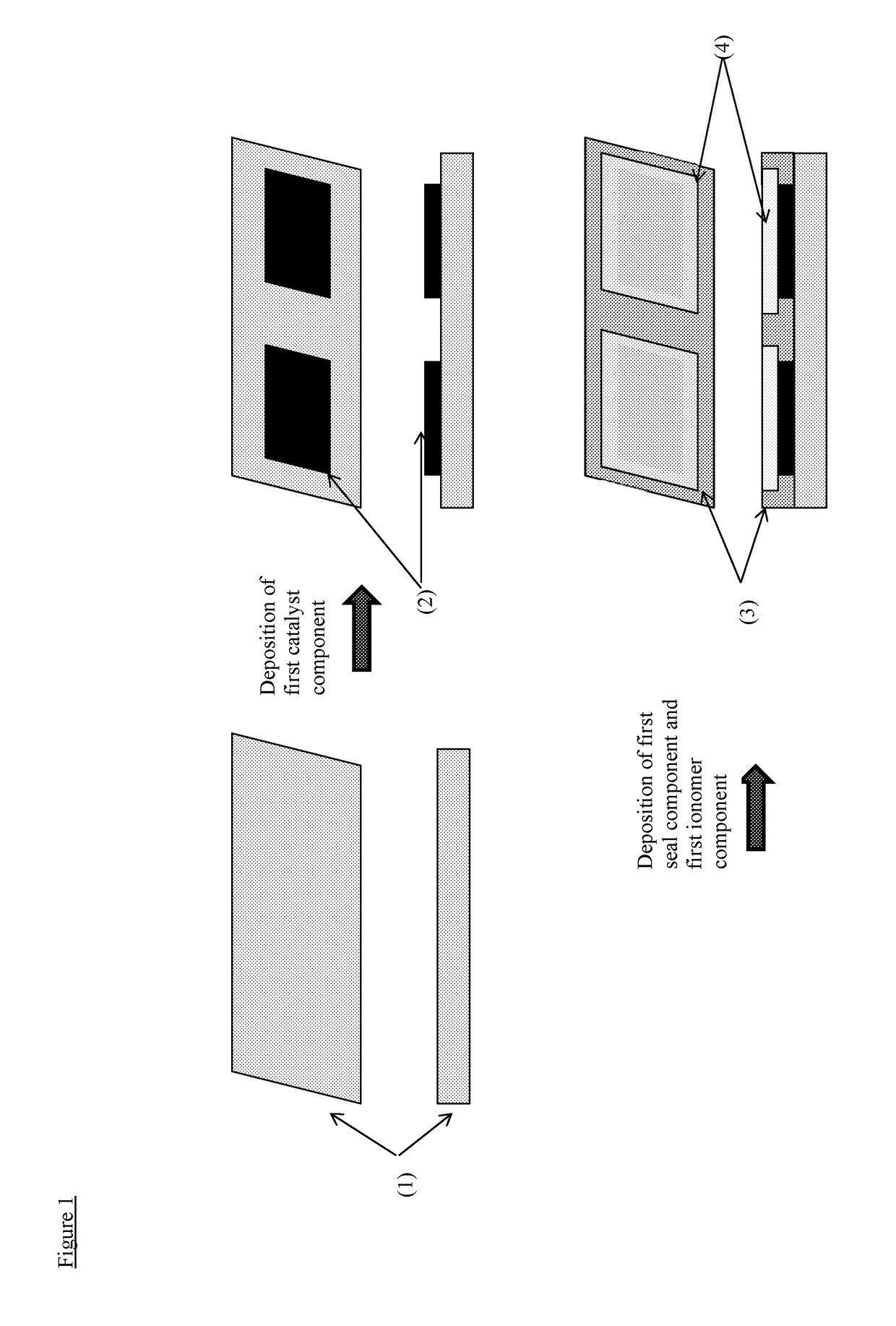
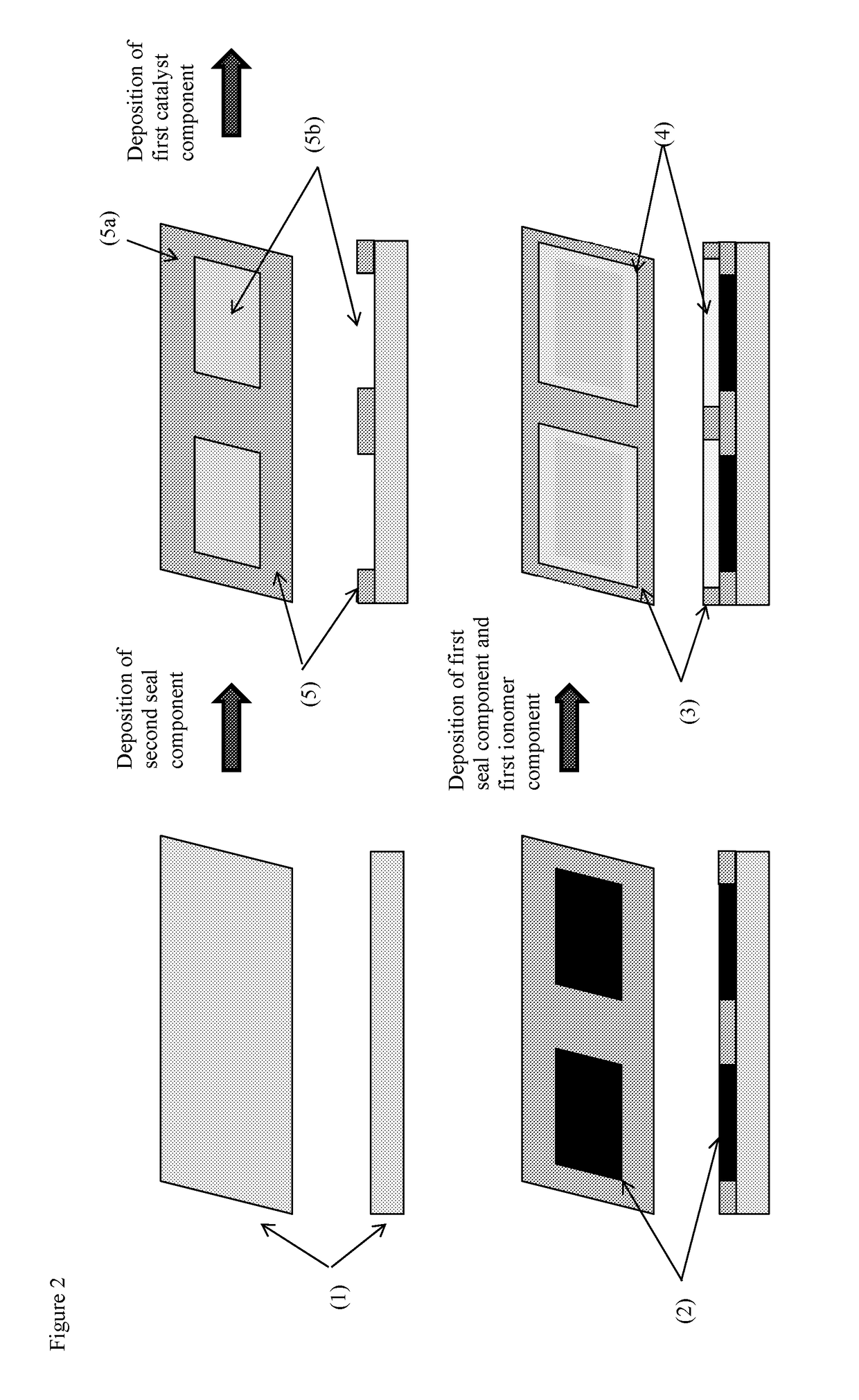
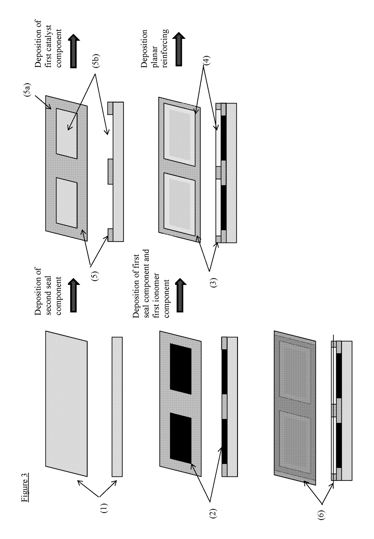
[0026]The invention provides a process for the manufacture of a catalyst-coated membrane-seal assembly, said process comprising the steps of:

[0027](i) providing a carrier material;

[0028](ii-i) forming a first layer, said first layer being formed by:[0029](a) depositing a first catalyst component onto the carrier material such that the first catalyst component is deposited in discrete regions;[0030](b) drying the first layer;

[0031](ii-ii) forming a second layer, said second layer being formed by:[0032](a) depositing a first seal component, such that the first seal component provides a picture frame pattern having a continuous region and void regions, the continuous region comprising first seal component and the void regions being free from first seal component;[0033](b) depositing a first ionomer component onto the first layer, such that the first ionomer component is deposited in discrete regions; and[0034](c) drying the second layer;[0035]wherein the void regions of the first seal ...


PUM

PropertyMeasurementUnit
thicknessaaaaaaaaaa
thicknessaaaaaaaaaa
thicknessaaaaaaaaaa

Abstract

Disclosed is a process for the manufacture of a catalyst-coated membrane-seal assembly, including:
    • (i) providing a carrier material;
    • (ii-i) forming a first layer, the first layer being formed by:
      • (a) depositing a first catalyst component onto the carrier material such that the first catalyst component is deposited in discrete regions;
      • (b) drying the first layer;
    • (ii-ii) forming a second layer, the second layer being formed by:
      • (a) depositing a first seal component, such that the first seal component provides a picture frame pattern having a continuous region and void regions, the continuous region including second seal component and the void regions being free from second seal component;
      • (b) depositing a first ionomer component onto the first layer, such that the first ionomer component is deposited in discrete regions; and
      • (c) drying the second layer.

Description

FIELD OF THE INVENTION[0001]The present invention relates to a process for manufacturing a catalyst-coated membrane-seal assembly and in particular a catalyst-coated membrane-seal assembly suitable for use in a fuel cell or an electrolyser.BACKGROUND OF THE INVENTION[0002]A fuel cell is an electrochemical cell comprising two electrodes separated by an electrolyte. A fuel, such as hydrogen or an alcohol, such as methanol or ethanol, is supplied to the anode and an oxidant, such as oxygen or air, is supplied to the cathode. Electrochemical reactions occur at the electrodes, and the chemical energy of the fuel and the oxidant is converted to electrical energy and heat. Electrocatalysts are used to promote the electrochemical oxidation of the fuel at the anode and the electrochemical reduction of oxygen at the cathode.[0003]In the hydrogen-fuelled or alcohol-fuelled proton exchange membrane fuel cells (PEMFC), the electrolyte is a solid polymeric membrane, which is electronically insula...

Claims


Application Information

Patent Timeline
Patent Type & Authority Applications(United States)
IPC IPC(8): H01M8/0297H01M8/0273H01M4/92H01M4/88H01M4/90C25B9/23
CPCH01M8/0297H01M4/8828H01M4/9041H01M4/926H01M2008/1095H01M4/928H01M4/9091H01M8/0273H01M4/9075H01M4/8814H01M4/8825H01M4/8882H01M8/1004H01M4/886H01M4/8839H01M4/8835H01M4/8832Y02P70/50Y02E60/50C25B11/00C25B9/00
Inventor BARNWELL, DAVID EDWARDCOLEMAN, ROBERT JEFFREYDICKINSON, ANGUSSOARES, JORGE MANUEL CARAMELOSWEETLAND, LEE ALAN
Owner JOHNSON MATTHEY HYDROGEN TECH LTD
Why Eureka
Try Eureka