Dispensing assembly

a technology of dispensing assembly and assembly, which is applied in the direction of packaging, dairy packaging, packaging foodstuffs, etc., can solve the problems of unhygienic operating conditions, and achieve the effect of ensuring the seclusion of the ring member

Active Publication Date: 2019-03-12
RAPAK INC
View PDF69 Cites 13 Cited by
  • Summary
  • Abstract
  • Description
  • Claims
  • Application Information

AI Technical Summary

Problems solved by technology

This can lead to unhygienic operating conditions, and for instance bacterial build up.

Method used


Image

  • Dispensing assembly
  • Dispensing assembly
  • Dispensing assembly

Examples


Embodiment Construction

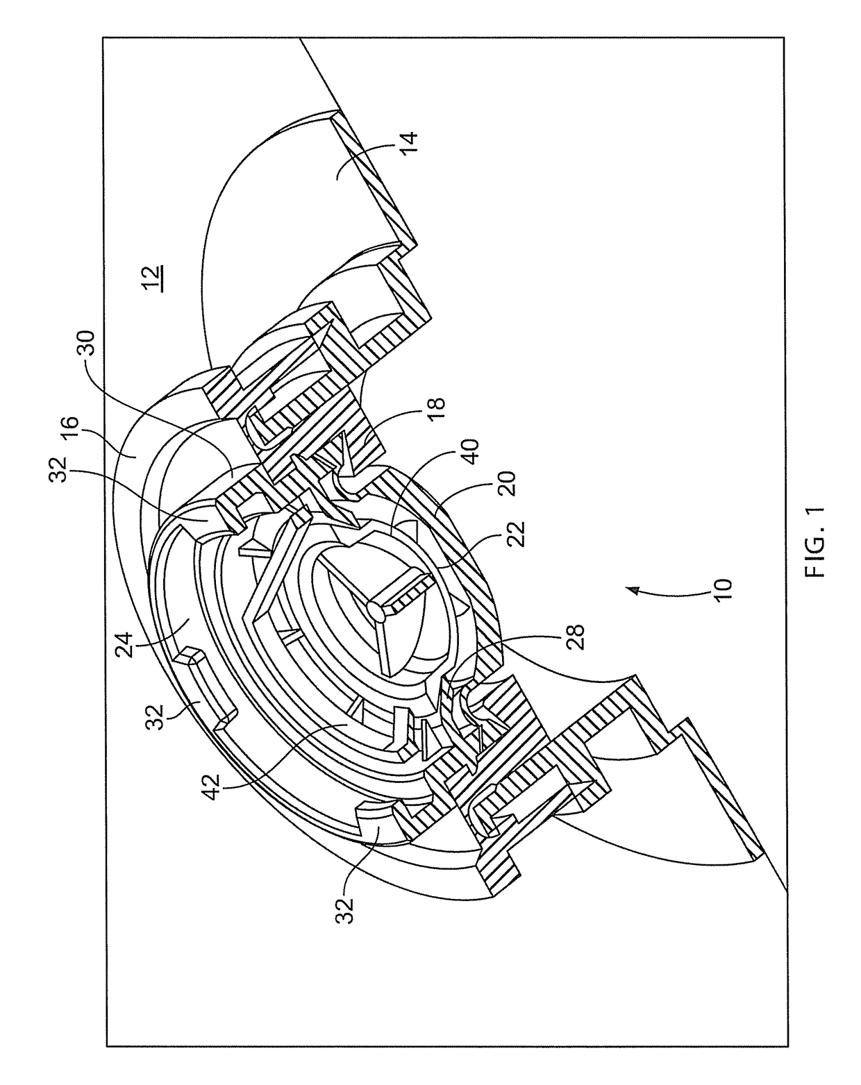
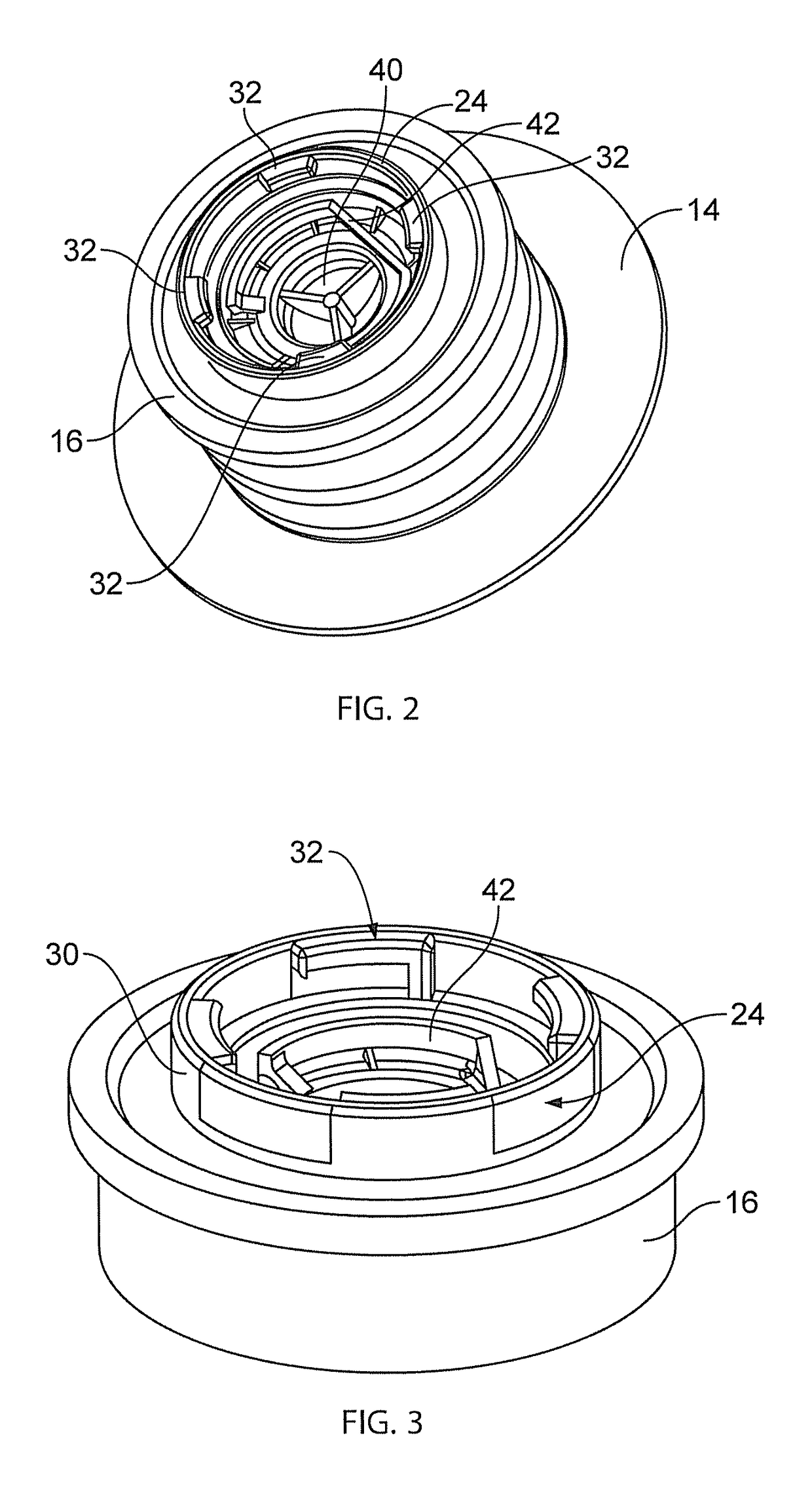
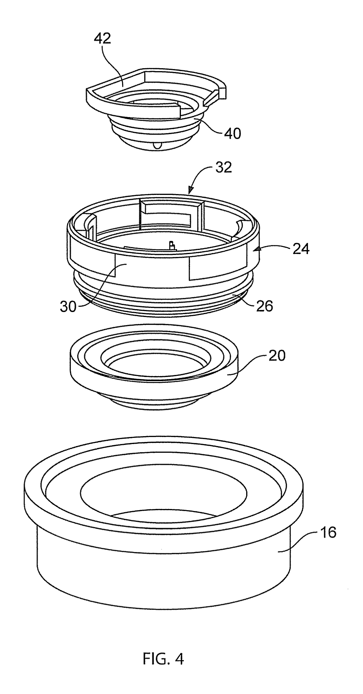
[0060]The drawings show a dispensing arrangement 10 for a liquid container such as a bag in a box arrangement for holding milk. Part of such a container 12 is shown in FIG. 1 with a spout 14. The arrangement 10 comprises a ring part 16 mountable on the spout 14 in a conventional arrangement. The ring part 16 provides an inwardly facing annular flange 18 on which sits a resilient membrane 20 which may be made for example of silicone. The membrane 20 has an opening configuration such as for example a cruciform or star shaped opening 22 provided centrally in it. The membrane 20 is configured such that in a rest position the opening configuration will remain closed thereby providing a seal for the arrangement 10.

[0061]A ring member 24 is provided which locates inside the ring part 16 and is a snap fit therein with a plurality of annular projections 26 on the ring member 24, which can be seen for instance in FIG. 5. The ring member 24 provides an inwardly turned annular flange 28 which h...


PUM


Abstract

A dispensing assembly for a liquid container including a ring part configured to be mounted to a liquid container, a resilient member positioned in the ring part to be in contact with the liquid contents of the liquid container, a ring member mountable to the ring part to secure the resilient member to the ring part, and a hollow connecting member with an outlet. The connecting member is releasably securable to the ring member and includes a hollow projecting member which, when the connecting member is secured to the ring member, engages the resilient member so as to urge an opening in the resilient member to permit liquid in the container to pass into the connecting member and subsequently out through the outlet.

Description

RELATED APPLICATIONS[0001]This application makes reference and claims priority to U.S. Provisional Patent Application No. 62 / 111,336, filed on Feb. 3, 2015 and titled “Dispensing Assembly,” and to Great Britain Patent Application No. 1417128.4, filed on Sep. 29, 2014 and titled “Dispensing Assembly.” U.S. Provisional Patent Application No. 62 / 111,336 and Great Britain Patent Application No. 1417128.4 are hereby incorporated by reference herein in their entireties.BACKGROUND OF THE INVENTION[0002]This invention concerns a dispensing assembly, a dispensing arrangement, and a container assembly of liquid.[0003]It is often required to provide a supply of a liquid such as milk to a drinks dispensing machine such as a coffee machine or otherwise. Previously this has often been achieved by filling a part of the machine with for instance milk. In view of the relatively short shelf life of liquids such as milk, it is appropriate for such parts of the machine to be regularly emptied and thoro...

Claims


Application Information

Patent Timeline
Patent Type & Authority Patents(United States)
IPC IPC(8): B65D47/06B65D77/06B65D85/80
CPCB65D47/068B65D85/80B65D77/067B65D77/065
Inventor DARBY, IANGEORGELOS, PAUL N.SMITH, MARK A.
Owner RAPAK INC
Why Eureka
Try Eureka