Reinforcement plate for an auxiliary state leaf pack of a leaf spring system

a technology of auxiliary leaf pack and leaf spring system, which is applied in the field of vehicle components, can solve the problems of component fatigue, auxiliary leaf pack is prone to higher vibration and associated noise, and needs more frequent inspection and/or replacemen

Active Publication Date: 2019-05-14
GM GLOBAL TECH OPERATIONS LLC
View PDF16 Cites 2 Cited by
  • Summary
  • Abstract
  • Description
  • Claims
  • Application Information

AI Technical Summary

Benefits of technology

[0002]Many wheeled vehicles include systems that absorb vibrations and accommodate vehicle loads. For example, a wheeled vehicle may include a leaf spring system that supports and sets a desired position of a vehicle axle. The leaf spring also bends and flexes in response to road conditions. Bending and flexing of the leaf spring reduces shocks and / or vibrations that may be perceived by a passenger. In operation, leaf springs are exposed to vibrations which may, over time, lead to component fatigue.
[0003]Vehicles that carry heavy loads may include an auxiliary leaf assembly having an auxiliary stage leaf pack coupled to the leaf spring system. The auxiliary stage leaf pack works with the leaf spring system to support heavier weights. The auxiliary stage leaf pack is prone to higher levels of vibration and associated noise. The higher levels of vibration lead to a need for more frequent inspection and / or replacement. Accordingly, it is desirable to provide a system that reduces the effects of vibration stress and also reduces noise generated by interactions between the wheeled vehicle and a road for an auxiliary stage leaf pack of a leaf spring system.SUMMARY

Problems solved by technology

In operation, leaf springs are exposed to vibrations which may, over time, lead to component fatigue.
The auxiliary stage leaf pack is prone to higher levels of vibration and associated noise.
The higher levels of vibration lead to a need for more frequent inspection and / or replacement.

Method used


Image

  • Reinforcement plate for an auxiliary state leaf pack of a leaf spring system
  • Reinforcement plate for an auxiliary state leaf pack of a leaf spring system
  • Reinforcement plate for an auxiliary state leaf pack of a leaf spring system

Examples


Embodiment Construction

[0026]The following description is merely exemplary in nature and is not intended to limit the present disclosure, its application or uses. It should be understood that throughout the drawings, corresponding reference numerals indicate like or corresponding parts and features.

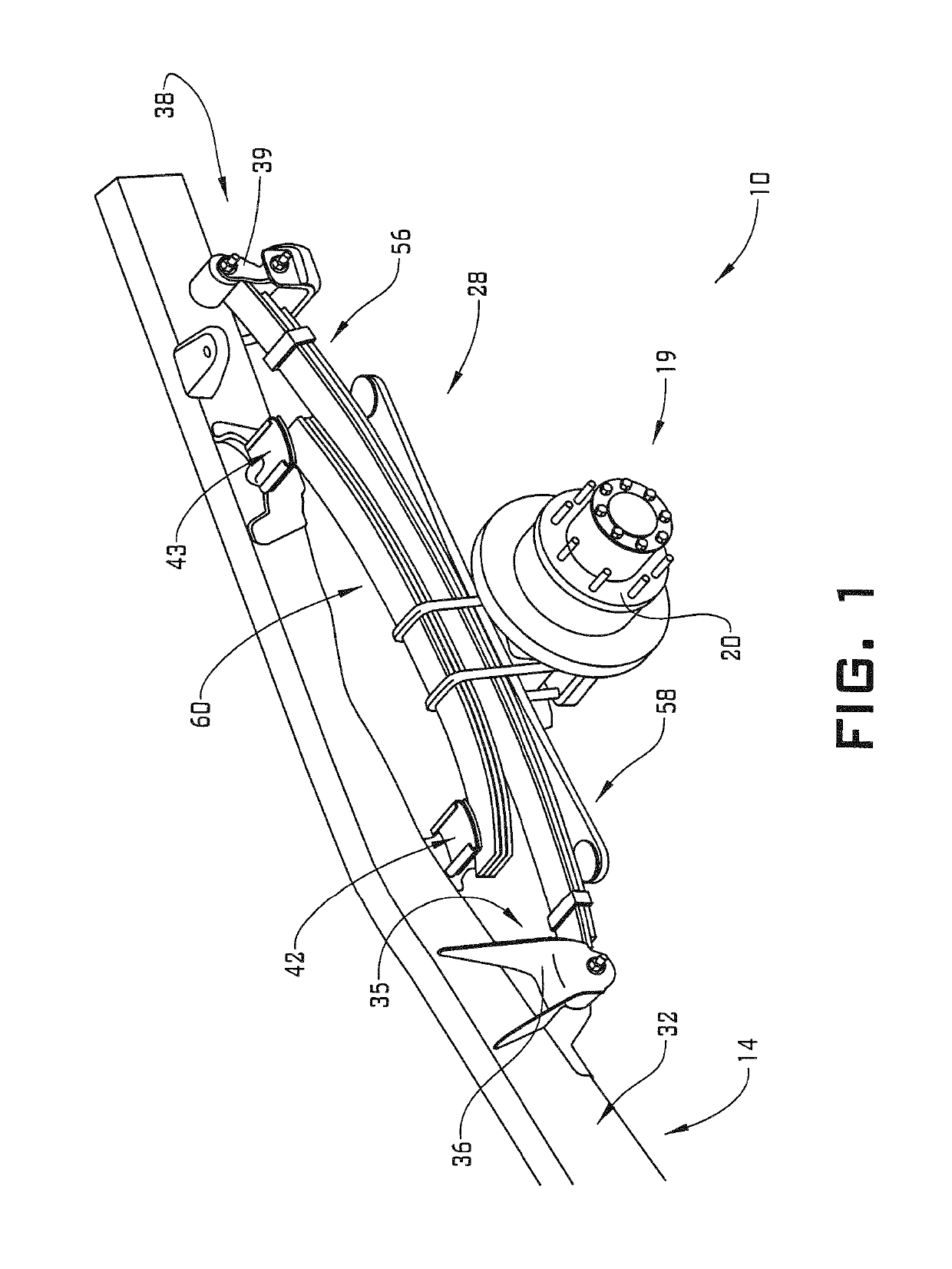
[0027]A vehicle, in accordance with an exemplary embodiment, is indicated generally at 10 in FIG. 1. It is to be understood that vehicle 10 may take on a variety of forms including powered vehicles such as trucks, pick-up trucks, and towed vehicles. Vehicle 10 includes a frame 14 that supports a body (not shown) and an axle assembly 19. Axle assembly 19 includes a hub 20 that is rotatably connected to a pair of wheels (also not shown). Axle assembly 19 is mechanically connected to frame 14 by a leaf spring system 28. While only showing a single leaf spring system, it is to be understood that axle assembly 19 is also supported by a second leaf spring system (not shown).

[0028]Frame 14 includes a plurality of fram...


PUM


Abstract

A leaf spring system includes a main leaf pack having a main leaf spring including a first end, a second and a first surface and a second opposing surfaces extending therebetween. An auxiliary stage leaf pack is arranged at the first. The auxiliary stage leaf pack includes a first surface portion and a second, opposing surface portion. A spacer is arranged between the first surface of the main leaf spring and the second surface portion of the auxiliary stage leaf pack. The spacer includes first axial end, a second axial end. A reinforcement plate is arranged at the first surface portion of the auxiliary stage leaf pack substantially aligned with the spacer. The reinforcement plate includes a first end section, a second end section. At least one of the first end section and the second end section extends beyond a corresponding one of the first and second axial ends.

Description

INTRODUCTION[0001]The subject disclosure relates to the art of vehicles and, more particularly, to a reinforcement plate for an auxiliary leaf system of a leaf spring system.[0002]Many wheeled vehicles include systems that absorb vibrations and accommodate vehicle loads. For example, a wheeled vehicle may include a leaf spring system that supports and sets a desired position of a vehicle axle. The leaf spring also bends and flexes in response to road conditions. Bending and flexing of the leaf spring reduces shocks and / or vibrations that may be perceived by a passenger. In operation, leaf springs are exposed to vibrations which may, over time, lead to component fatigue.[0003]Vehicles that carry heavy loads may include an auxiliary leaf assembly having an auxiliary stage leaf pack coupled to the leaf spring system. The auxiliary stage leaf pack works with the leaf spring system to support heavier weights. The auxiliary stage leaf pack is prone to higher levels of vibration and associ...

Claims


Application Information

Patent Timeline
Patent Type & Authority Patents(United States)
IPC IPC(8): F16F1/30B60G11/04F16F3/02
CPCB60G11/04F16F3/023F16F1/30B60G2204/121
Inventor CHEN, JIANBASIN, OLEG G.
Owner GM GLOBAL TECH OPERATIONS LLC
Why Eureka
Try Eureka