
Image forming apparatus having vibration reducing member

Inactive Publication Date: 2007-02-22
SAMSUNG ELECTRONICS CO LTD
View PDF2 Cites 22 Cited by
  • Summary
  • Abstract
  • Description
  • Claims
  • Application Information

AI Technical Summary

Benefits of technology

[0009] The present invention provides an image forming apparatus that reduces shock or vibration transferred to a developing roller to substantially prevent jitter generation and printing failure caused thereby.
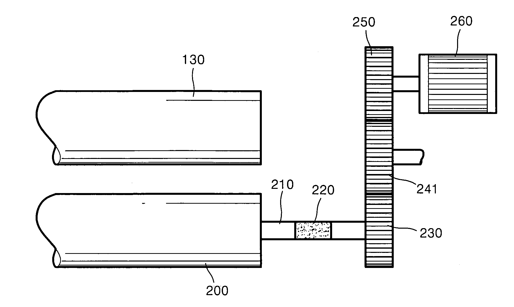
[0010] According to an aspect of the present invention, an image forming apparatus includes a photosensitive member on which an electrostatic latent image is formed. A developing unit that develops the electrostatic latent image by the use of developing materials and that includes a developing roller that rotates about the rotation axis thereof, in which the developing roller faces the photo-sensitive member. A vibration reducing member reduces vibration in the rotation direction of the developing roller.
[0011] The vibration reducing member may reduce the vibration in the rotation direction of the developing roller by changing the natural frequency in the rotation direction of the developing roller to be less than the exciting frequency in the rotation direction of the developing roller.

Problems solved by technology

When the rotation speed jitters, printing quality deteriorates.
In particular, when printing an image, such as a picture or a photograph, the printing quality deterioration stemming from the jitter increases.
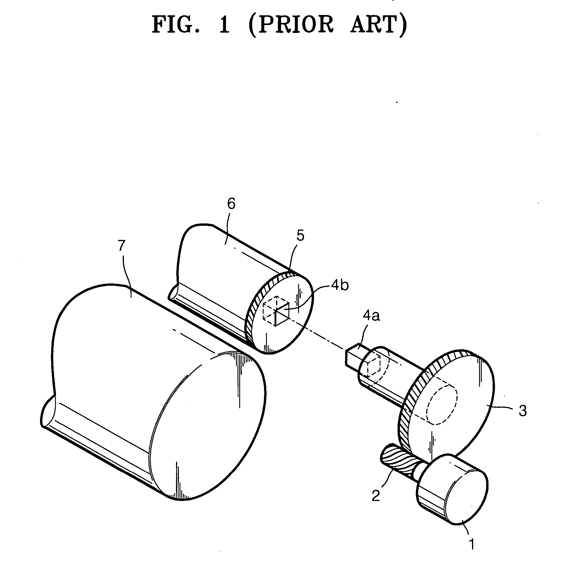
In particular, the shock or vibration generated inwardly in the driving unit is a cause of the jitter when the shock or the vibration is transmitted to the developing roller 6 rotating at a constant speed.

Method used


Image

  • Image forming apparatus having vibration reducing member
  • Image forming apparatus having vibration reducing member
  • Image forming apparatus having vibration reducing member

Examples


Embodiment Construction

[0026] Hereinafter, exemplary embodiments of the present invention are described in detail with reference to the accompanying drawings. The exemplary embodiments of the present invention, however, are not limited thereto but various changes in form and details may be made therein without departing from the spirit and scope of the present invention.

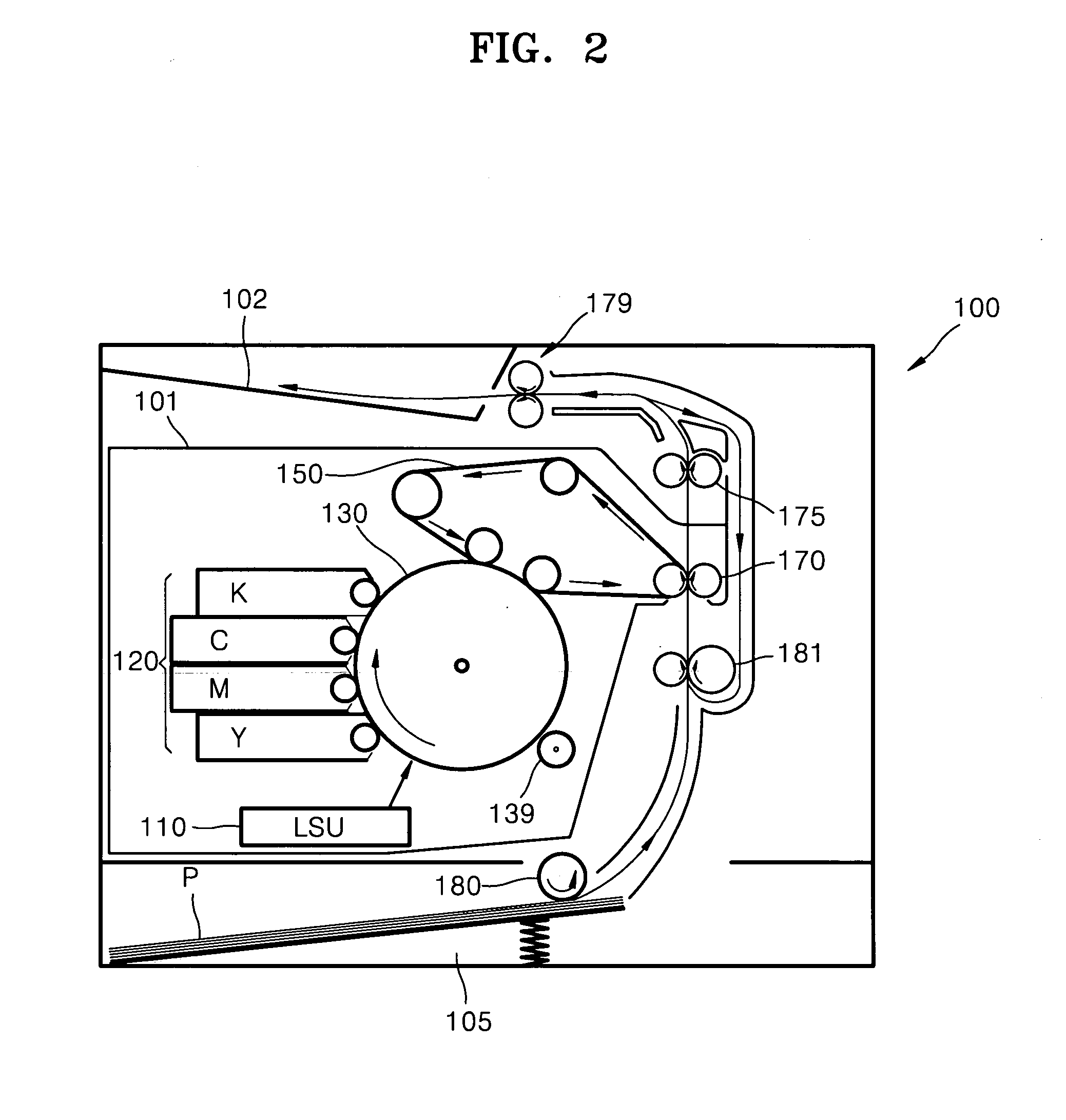
[0027]FIG. 2 is a side elevational view of an image forming apparatus 100 according to an exemplary embodiment of the present invention. Referring to the drawing, a printing unit 101 for printing an image onto a printing medium P and a fixing unit 175 for fusing the printed image onto the printing medium P are provided. The printing unit 101 includes a charging unit 139, a laser scanning unit (LSU) 110, a photosensitive member 130, a developing unit 120, an intermediate transfer belt 150, and a transfer belt 170. For color printing, the printing unit 101 provides four developing units 120 containing developing materials of black K, cyan C...


PUM


Abstract

An image forming apparatus having a vibration reducing member is provided. The image forming apparatus includes a photosensitive member, a developing roller, an axis of the developing roller, and a gear train for driving the developing roller. Accordingly, the quality of print image is improved by providing the vibration reducing member in which the natural frequency in the rotation direction of the developing roller is less than the exciting frequency in the direction of the developing roller.

Description

CROSS-REFERENCE TO RELATED PATENT APPLICATION [0001] This application claims the benefit under 35 U.S.C §119(a) of Korean Patent Application No. 10-2005-0076963, filed on Aug. 22, 2005, in the Korean Intellectual Property Office, the entire disclosure of which is hereby incorporated by reference. BACKGROUND OF THE INVENTION [0002] 1. Field of the Invention [0003] The present invention relates to an image forming apparatus. More particularly, the present invention relates to an electrophotographic image forming apparatus that reduces vibration in the rotation direction of a developing roller. [0004] 2. Description of the Related Art [0005] Generally, electrophotographic image forming apparatuses carry out a series of printing operations in which light is illuminated onto a photosensitive member to form an electrostatic latent image corresponding to a print image. The electrostatic latent image is developed in a developing unit with a developing material. The developed toner image is ...

Claims


Application Information

Patent Timeline
IPC IPC(8): G03G15/06G03G15/08
CPCG03G15/0896G03G15/06G03G15/0822G03G15/757G03G2221/1657
Inventor KIM, JONG-TAEKIM, SUNG-DAE
Owner SAMSUNG ELECTRONICS CO LTD
Learn More