Method for producing a printing material and a directly printed decorative panel

a printing substrate and decorative panel technology, applied in the direction of decorative arts, decorative articles, lamination, etc., can solve the problems of increased production costs, no optimal printing substrate surface for decorative panels to be printed, and problems such as adhesion problems of printing ink

Active Publication Date: 2019-07-02
SURFACE TECH
View PDF27 Cites 13 Cited by
  • Summary
  • Abstract
  • Description
  • Claims
  • Application Information

AI Technical Summary

Benefits of technology

[0015]Thus it is an object of the present invention to provide a method for producing a printing substrate for direct printing onto a decorative panel, which is able to overcome the problem known in the prior art. Moreover, it is an object of the present invention to provide a decorative panel with a corresponding printing substrate. In particular, it is an object of the present invention to provide a method for producing a directly printed decorative panel without backing layer and to provide a corresponding decorative panel without backing layer.

Problems solved by technology

Herein, the application of the backing layer requires a further process step and, thus, increased production costs.
A problem which may occur during direct printing of decorative panels is that the surface of the decorative panel to be printed is no optimal printing substrate onto which a corresponding decor can be applied.
Here, the problem is that a paper or non-woven fabric layer applied as a printing substrate onto a carrier plate of a decorative panel is penetrated by the resin used for the application such that the resin applied for fixing penetrates through on the side of the paper or non-woven fabric intended to be printed and can cause adhesion problems of the printing ink there.
However, such a barrier layer often brings about that the ink applied in the printing process does not or not sufficiently settle into the paper or non-woven fabric, but remains on the surface, which adversely affects the quality of the print.
However, during the subsequent application of a top or wearing layer adhesion problems can be caused, so that the final composite laminate has no sufficient stability and, for example, splitting of the laminate in the decorative paper layer is caused.

Method used


Image

  • Method for producing a printing material and a directly printed decorative panel
  • Method for producing a printing material and a directly printed decorative panel

Examples


Embodiment Construction

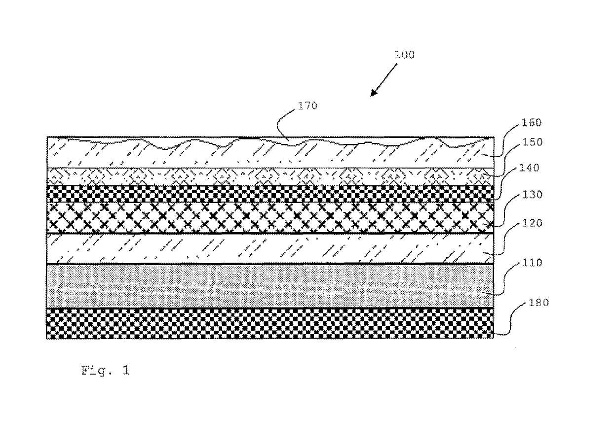
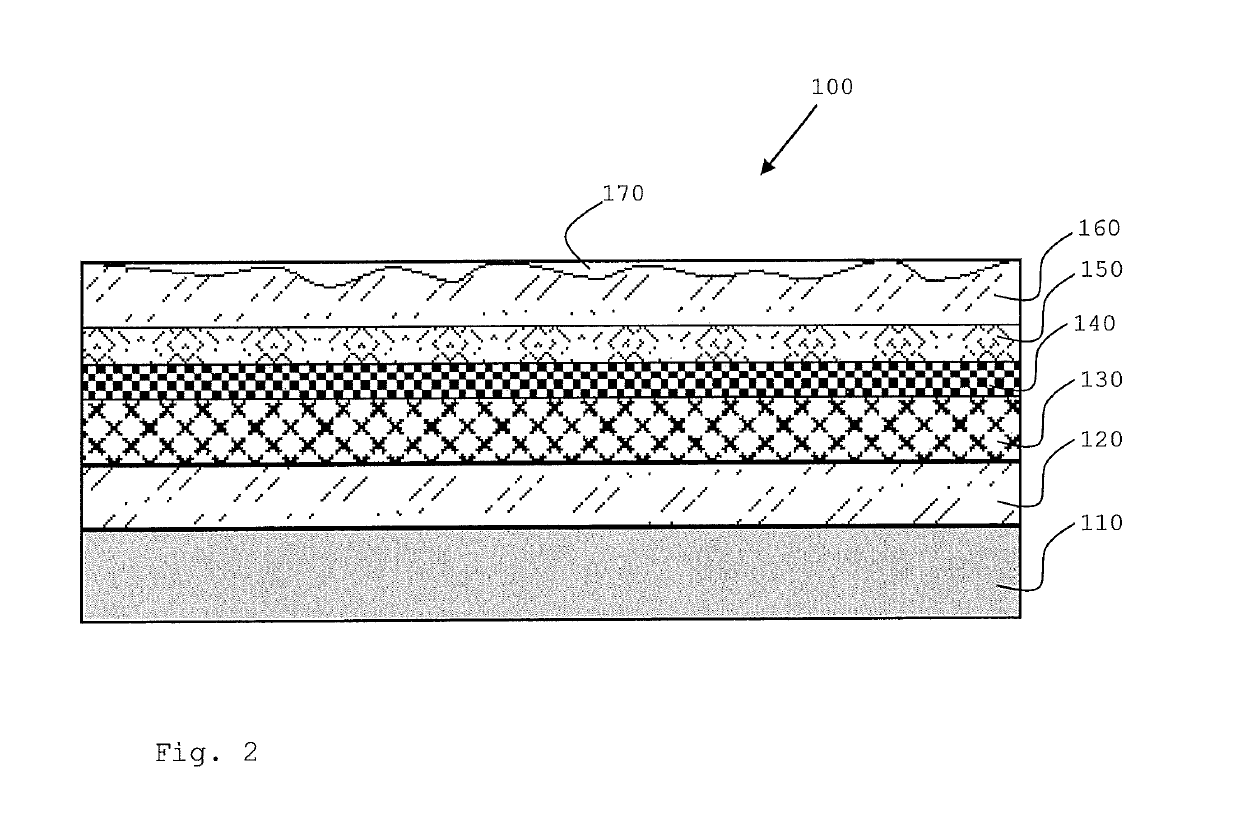
[0019]Thus, according to the present invention a method for producing a printing substrate for direct printing onto a decorative panel is proposed, comprising the steps:[0020]a) providing a plate-shaped carrier;[0021]b) applying a resin layer onto the plate-shaped carrier;[0022]c) applying an unprinted paper or non-woven fabric layer onto the plate-shaped carrier; and[0023]d) calendering the laminate structure obtained at a temperature between ≥40° C. and ≤250° C., characterized in that after the calendering process a resin composition is applied including between ≥0.5 wt.-% and ≤85 wt.-%, preferably between ≥1.0 wt.-% and ≤80 wt.-% of a solid material having a mean grain diameter d50 between ≥0.1 μm and ≤120 μm, preferably between ≥1 μm and ≤100 μm.

[0024]It has surprisingly been found that the application of a printing substrate with a corresponding solid material content after calendering an unprinted paper or non-woven fabric layer is adapted to provide a surface excellently suit...


PUM

PropertyMeasurementUnit
temperatureaaaaaaaaaa
mean grain diameter d50aaaaaaaaaa

Abstract

Method for producing a printing substrate for direct printing onto a decorative panel, comprising the steps of providing a plate-shaped carrier; applying a resin layer onto the plate-shaped carrier; applying a paper or non-woven fabric layer onto the plate-shaped carrier; and calendering the resulting layered structure at a temperature between ≥40° C. and ≤250° C.; wherein after the calendering process a resin composition is applied, which comprises between ≥0.5 wt.-% and ≤85 wt.-% of a solid material having a mean grain diameter d50 between ≥0.1 μm and ≤120 μm.

Description

REFERENCE TO RELATED APPLICATIONS[0001]This application is a U.S. national stage application of International Patent Application No. PCT / EP2013 / 075627, filed Dec. 5, 2013, and claims the benefit of priority of European Application No. 13177791.4, filed Jul. 24, 2013 and European Application No. 12199682.1 filed Dec. 28, 2012, the entire disclosures of which are incorporated herein by reference.FIELD OF THE INVENTION[0002]The present invention relates to a method for producing a printing substrate for direct printing on a decorative panel. Moreover, the present invention relates to a decorative panel comprising a printing substrate produced according to a method according to the invention. The present invention in particular relates to a method for producing a directly printed decorative panel without backing layer and a decorative panel without backing layer produced according to a method according to the present invention.BACKGROUND[0003]The term “decorative panel” in the sense of ...

Claims


Application Information

Patent Timeline
Patent Type & Authority Patents(United States)
IPC IPC(8): B32B5/02B32B38/00B32B27/10B32B27/12B32B29/00B44C5/04
CPCB32B5/022B32B27/10B32B27/12B32B29/002B44C5/04B32B38/145B32B2607/00B32B2307/75B32B2451/00B32B2471/00B32B38/14B32B29/00
Inventor HANNIG, HANS-JURGEN
Owner SURFACE TECH
Why Eureka
Try Eureka