Eureka AIR delivers breakthrough ideas for toughest innovation challenges, trusted by R&D personnel around the world.

Image forming apparatus, image forming method, and program

a technology of image forming and forming methods, applied in the field of image forming apparatuses, image forming methods, and programs, can solve the problems of deterioration in productivity, deterioration of productivity, and varies in image quality of output images (image output to a sheet), so as to reduce toner consumption and productivity deterioration

Active Publication Date: 2019-07-02
KONICA MINOLTA INC
View PDF11 Cites 0 Cited by
  • Summary
  • Abstract
  • Description
  • Claims
  • Application Information

AI Technical Summary

Benefits of technology

The present invention aims to solve the calibration issues in image forming apparatuses that cause toner consumption and reduced productivity. The technical effects of this invention include significantly improved accuracy in calibration, reduced toner usage, and improved productivity.

Problems solved by technology

In the image forming apparatus, there is a problem that an image quality of an output image (image output to a sheet) varies due to deterioration of the photoconductor drum, a developer, and the like with the passage of time, an environment (a fluctuation in temperature and humidity), and the like at the periphery of the apparatus.
However, in the calibration described in JP 2008-224845 A and JP 11-075067 A, it is necessary to stop another job so as to perform the test printing of the patch for test, and thus deterioration in productivity is caused.
In addition, there is a problem that toner consumption increases due to the test printing of the patch for test.
However, in this case, a color or a gradation, which can be acquired as data for calibration, is limited to the color information of the input image data for which the printing command is actually issued.
As a result, there is a problem that it is difficult to acquire data for calibration related to necessary and sufficient color information, and it is difficult to perform calibration with accuracy.

Method used


Image

  • Image forming apparatus, image forming method, and program
  • Image forming apparatus, image forming method, and program
  • Image forming apparatus, image forming method, and program

Examples


first embodiment

[0039][Configuration Example of Image Forming Apparatus]

[0040]First, description will be given of an image forming apparatus 1 according to this embodiment. Furthermore, the image forming apparatus 1 according to this embodiment is applied to a copier, a printer, a facsimile, and the like.

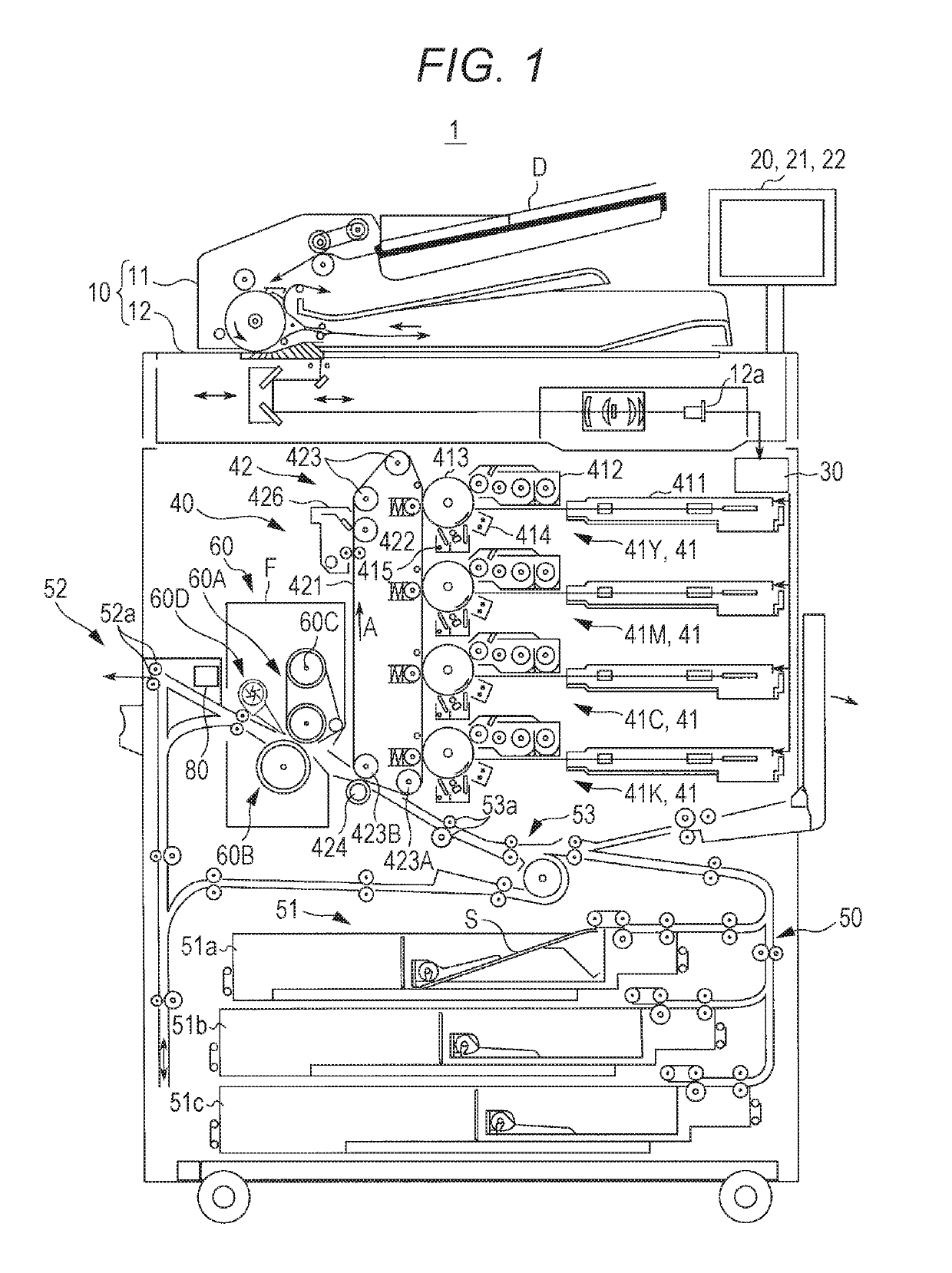
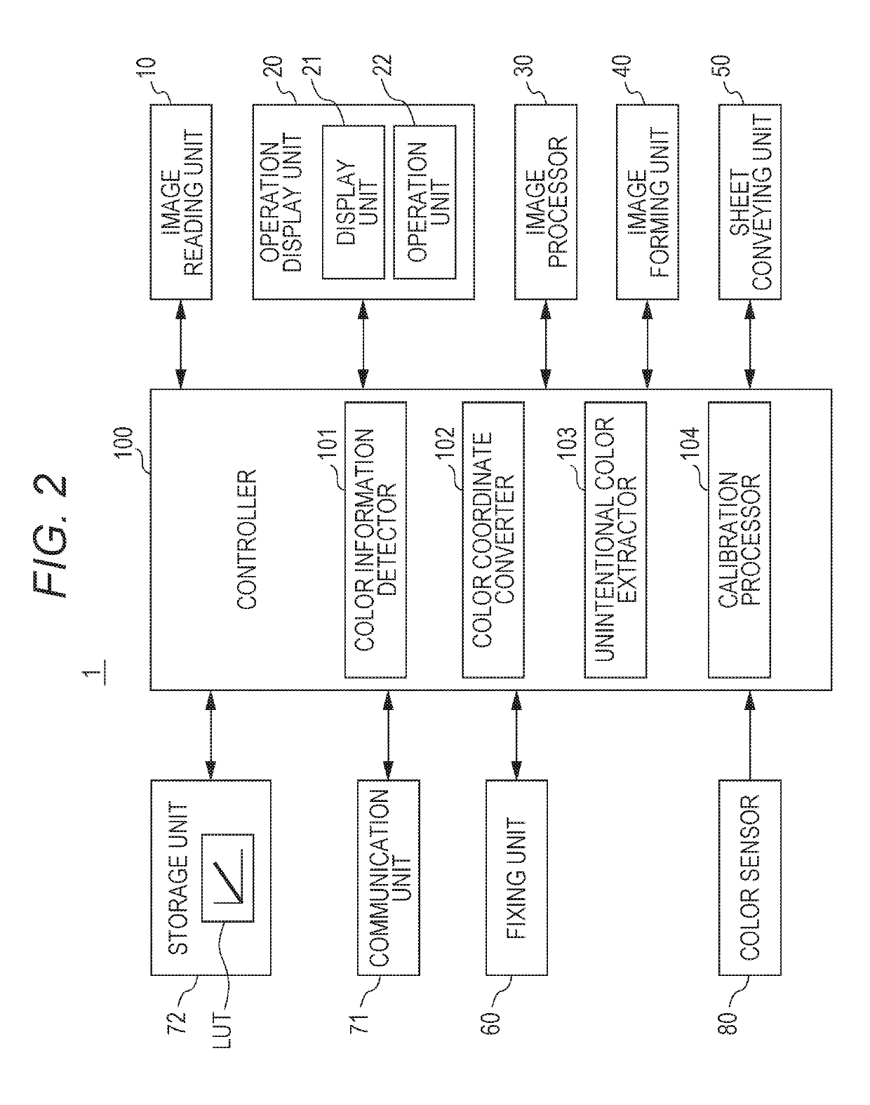
[0041]FIG. 1 and FIG. 2 are views schematically illustrating an overall configuration of the image forming apparatus 1 according to the first embodiment.

[0042]The image forming apparatus 1 illustrated in FIG. 1 is an intermediate transfer type color image forming apparatus using an electrophotographic process technology. That is, the image forming apparatus 1 primarily transfers toner images, which are respectively formed on photoconductor drums 413, of respective colors of yellow (Y), magenta (M), cyan (C), and Hack (K) to an intermediate transfer belt 421, and the toner images of four colors are superimposed on an intermediate transfer belt 421 and are secondarily transferred to a sheet S to form...

second embodiment

[0135]Next, an image forming apparatus 1 according to a second embodiment will be described with reference to FIGS. 10A to 14.

[0136]The image forming apparatus 1 according to this embodiment is different form the first embodiment in that when the unintentional color extractor 103 corrects color information of a pixel region in which input image data is present, the correction is also performed with respect to a pixel region on the other side of the contour regions in addition to the pixel region. Furthermore, description of a configuration that is common to the first embodiment will be omitted (hereinafter, this is also true of other embodiments).

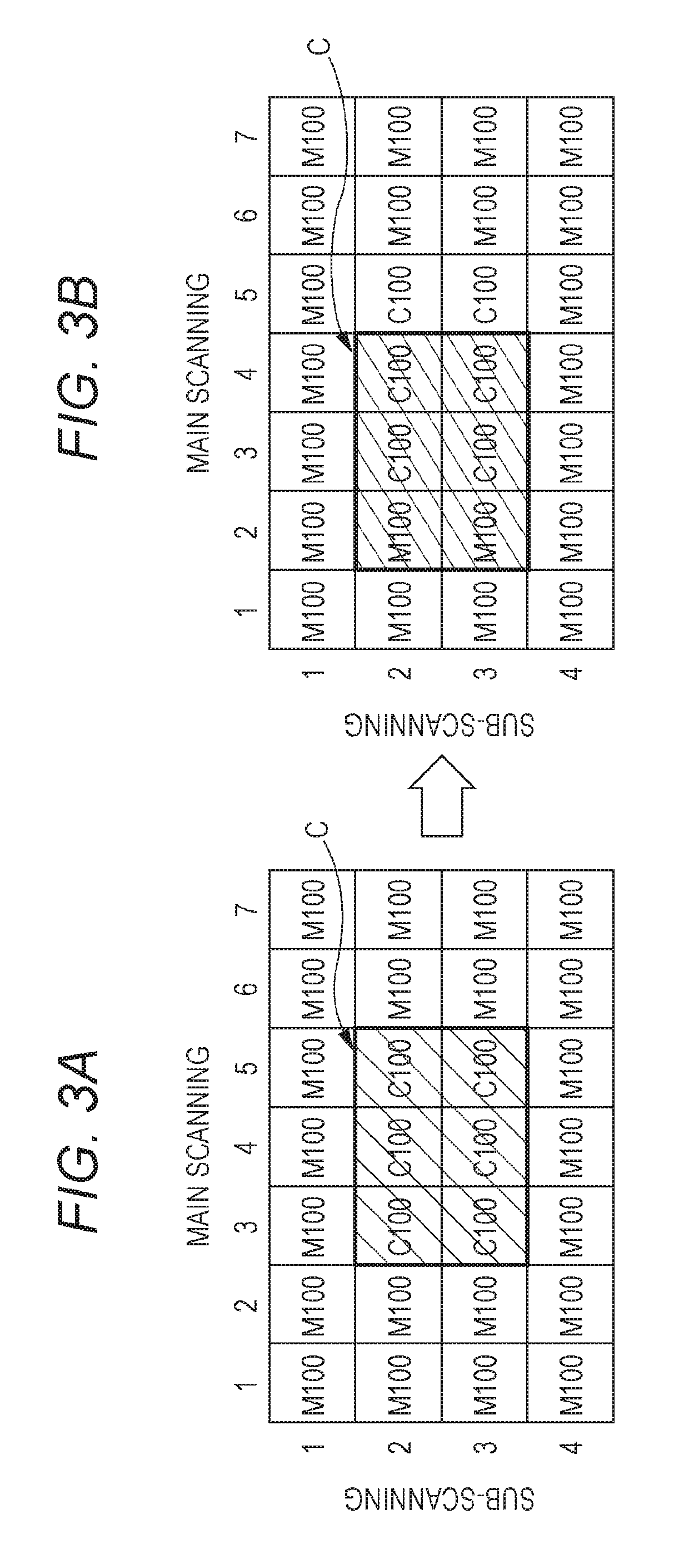
[0137]Typically, a color variation caused by the color deviation or the toner scattering occurs not only in one pixel region but also in an adjacent pixel region. From this viewpoint, when performing correction of the color information with respect to a predetermined pixel region in the input image data, the image forming apparatus 1 accord...

third embodiment

[0158]Next, an image forming apparatus 1 according to a third embodiment will be described with reference to FIGS. 15 to 18.

[0159]This embodiment is different from the first embodiment in that when performing correction of color information of input image data, the unintentional color extractor 103 adjusts the amount of correction when performing correction on the basis of color information of an output image in non-contour regions.

[0160]Occurrence of a color variation in an output image may be caused by a state variation (also referred to as “engine performance”) of the image forming unit 40 without limitation to the color deviation or the toner scattering. From this viewpoint, the image forming apparatus 1 according to this embodiment detects the state variation of the image forming unit 40 on the basis of a variation of color information of an output image with respect to color information of input image data in non-contour regions in which color information is the same between a...


PUM


Abstract

An image forming apparatus that forms an output image corresponding to input image data on an image carrier by superimposing toner images of colors, includes a hardware processor that: detects color information of the output image for every pixel region; converts color information of the input image data for every pixel region and color information of the output image for every pixel region into indexes which define colors in predetermined color space coordinates; extracts a pixel region in which the color information of the output image is different from the color information of the input image data, and corrects the color information of the input image data with respect to the extracted pixel region; and stores the color information of the input image data as data for calibration in combination with the color information of the output image and image forming conditions when forming the output image.

Description

[0001]The entire disclosure of Japanese patent Application No. 2017-094921, filed on May 11, 2017, is incorporated herein by reference in its entirety.BACKGROUNDTechnological Field[0002]The present disclosure relates to an image forming apparatus, an image forming method, and a program.Description of the Related Art[0003]In the related art, in color image forming apparatus (a copier, a printer, a facsimile, and the like) using an electrophotographic process technology, an intermediate transfer method using an intermediate transfer body such as an intermediate transfer belt becomes the main stream. The intermediate transfer method is a method in which toner images, which are respectively formed on photoconductor drums, of respective colors of C (cyan), magenta (M), yellow (Y), black (K), and the like are transferred (primarily transferred) to the intermediate transfer body, and the toner images of four colors are superimposed on the intermediate transfer body and are transferred (sec...

Claims


Application Information

Patent Timeline
Patent Type & Authority Patents(United States)
IPC IPC(8): H04N1/60H04N1/58
CPCH04N1/6027H04N1/58H04N1/6047H04N1/6019H04N1/603
Inventor KOORIYA, TAKAAKIYAMANAKA, DAIKIKIDERA, HIROSHIGE
Owner KONICA MINOLTA INC
Why Eureka
Eureka Blog
Learn More