
Imaging apparatus

a technology of imaging apparatus and spherical tube, which is applied in the field of imaging apparatus, can solve the problems of increasing the circuit scale and power consumption, size and cost, and the inability to use high-performance memory and microcomputers in some cases, and achieves the effect of high frame ra

Inactive Publication Date: 2014-06-26
CANON KK
View PDF7 Cites 0 Cited by
  • Summary
  • Abstract
  • Description
  • Claims
  • Application Information

AI Technical Summary

Benefits of technology

The present invention allows for recording of large, high-frame rate moving images while keeping the circuit size and power consumption low.

Problems solved by technology

However, the use of these high-performance memory and microcomputer leads to an increase in the circuit scale and the power consumption.
Especially, with regard to consumer digital cameras, there is demand for a reduction in size and cost as well as maximum suppression of the power consumption, and therefore a high-performance memory and microcomputer cannot be used in some cases.
This gives rise to the problem that moving images with a large number of pixels and a high frame rate cannot be captured.

Method used


Image

  • Imaging apparatus
  • Imaging apparatus
  • Imaging apparatus

Examples


Embodiment Construction

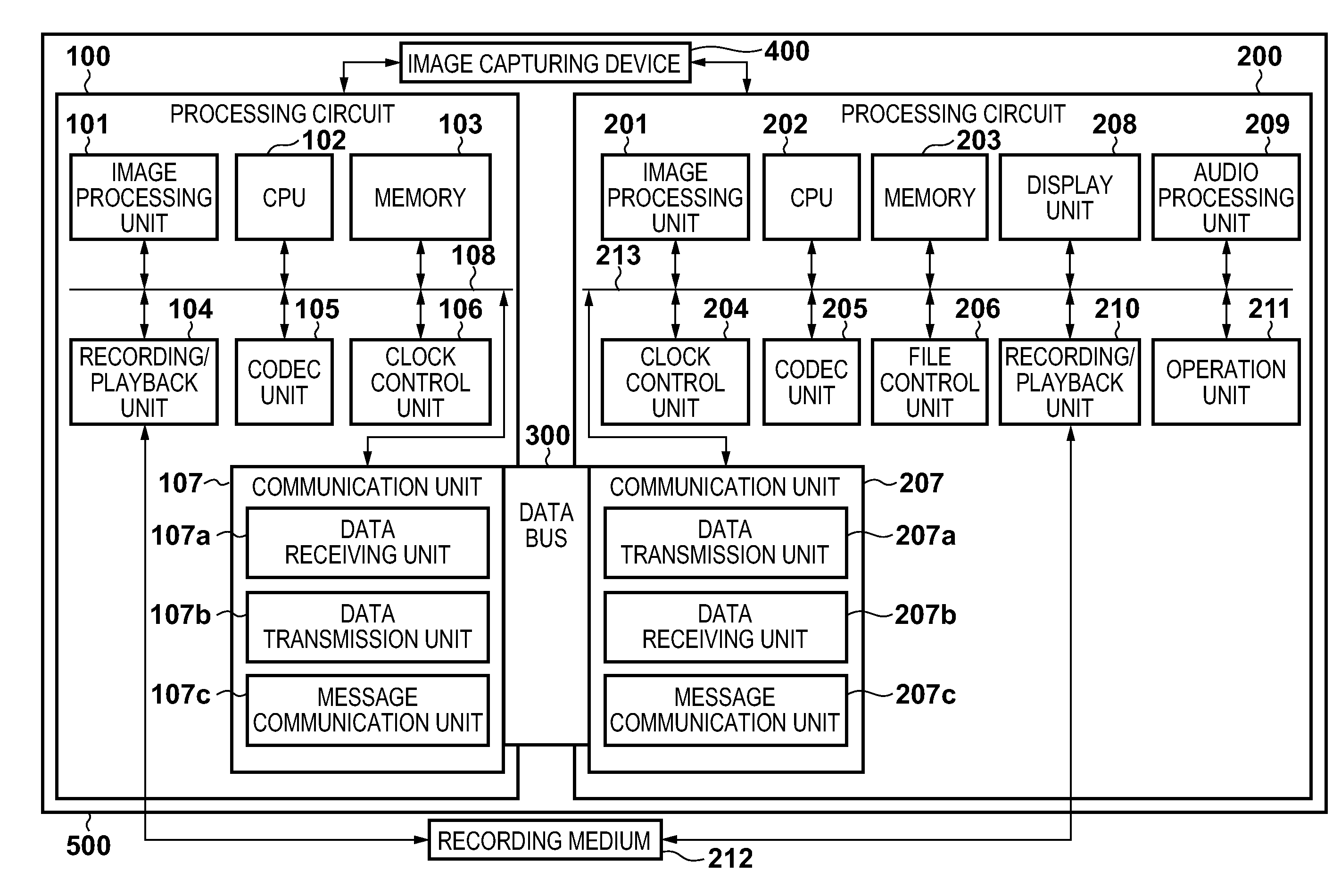
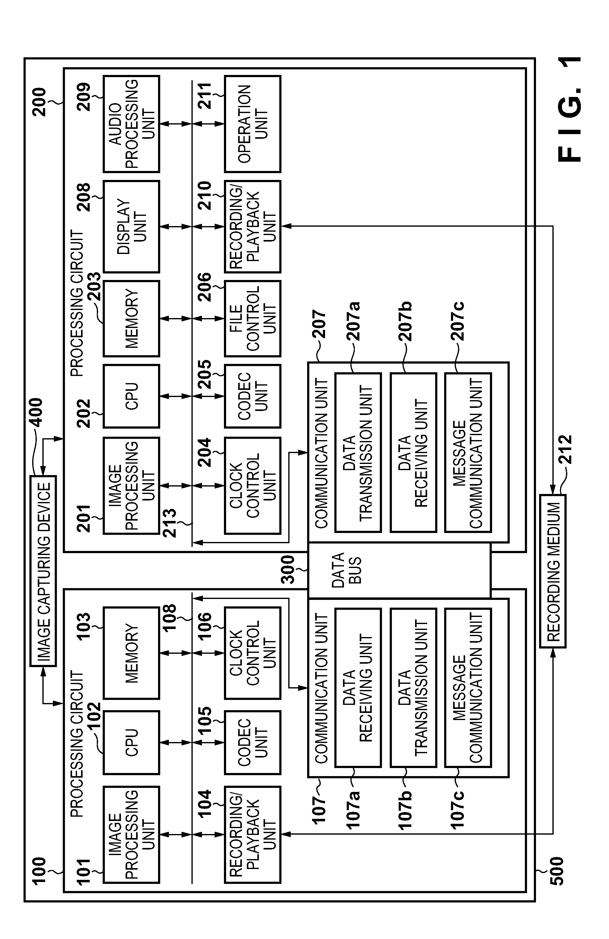
[0029]An embodiment of the present invention will be described below in detail with reference to the attached drawings. FIG. 1 is a block diagram showing an example of a configuration of an imaging apparatus 500 according to the present embodiment.

[0030]The imaging apparatus 500 includes two processing circuits, that is to say, a processing circuit 100 (first processing circuit) and a processing circuit 200 (second processing circuit). In the present embodiment, these two processing circuits 100 and 200 are each configured as a single integrated circuit (IC).

[0031]Furthermore, a dedicated bus 300 is provided, via which the two processing circuits 100 and 200 communicate with each other. Each of the processing circuits 100 and 200 can independently acquire moving image data from an image capturing device 400. Each of the processing circuits 100 and 200 can also process moving image data acquired from the image capturing device 400.

[0032]A description is now given of configurations of...


PUM


Abstract

This invention allows recording of moving images with a large number of pixels and high frame rate while suppressing the circuit scale and power consumption. A first processing circuit encodes a frame acquired from an image capturing device, records the resultant encoded data in a recording medium at a recording position received from a second processing circuit, and transmits a relevant data amount to the second processing circuit. The second processing circuit encodes a frame obtained from the image capturing device, records the resultant encoded data in the recording medium at a recording position determined in prior recording processing, determines a recording position for the first processing circuit, and transmits the determined recording position to the first processing circuit. Upon receiving information showing a data amount, the second processing circuit updates a recording position based on the received data amount.

Description

BACKGROUND OF THE INVENTION[0001]1. Field of the Invention[0002]The present invention relates to an imaging apparatus that captures moving images.[0003]2. Description of the Related Art[0004]Conventionally, digital cameras and other imaging apparatuses are known that capture moving images and record the captured moving images in a recording medium such as a memory card (for example, Japanese Patent Laid-Open No. 2005-101835). In recent years, some consumer digital cameras can capture moving images with a large number of pixels. Furthermore, a frame rate of captured moving images (the number of frames per unit time) is increasing.[0005]With an increase in the number of pixels and the frame rate of captured moving images, a data amount to be processed per unit time increases; this makes it necessary to process moving image data at a speed faster than ever.[0006]Improvements in the processing ability for moving image data require a memory that has a large storage capacity and can be ac...

Claims


Application Information

Patent Timeline
Patent Type & Authority Applications(United States)
IPC IPC(8): H04N9/79
CPCH04N5/772H04N9/8042H04N23/65H04N23/651H04N9/79
Inventor AOYAMA, YUUZOU
Owner CANON KK
Learn More