Auto-exposure for multi-imager barcode reader

a barcode reader and imager technology, applied in the field of bar code readers, can solve the problems of increasing the cost and power consumption of the sensor, not being able to achieve, and the sensor operating at higher frame rates is more expensive, so as to achieve the effect of putting a more of a load on the decoder, higher frame rates, and higher frame rates

Active Publication Date: 2010-10-07
SYMBOL TECH LLC
View PDF70 Cites 64 Cited by
  • Summary
  • Abstract
  • Description
  • Claims
  • Application Information

AI Technical Summary

Benefits of technology

[0011]A real-time auto-exposure system for a bar code reader having multiple imagers is disclosed wherein a number of imagers or cameras use a global shutter sensor. Imaging sensors having global shutters can expose the sensor for a small portion of an overall image capture frame time. This capability allows the illumination systems of different cameras of the multiple camera system to flash, without interference. In the disclosed system, multiple global shutter sensors are programmed to operate at the longest exposure time that is anticipated to be necessary for the scanning application. For example, the programmed exposure time would be adequate to decode a barcode at the maximum required working range, assuming that the reader's illumination system is illuminated for that entire exposure time.
[0012]The disclosed system makes optimum use of a limited number of captured image frames. It allows the camera sensor to operate at a minimum number of frames per second since every image will be properly exposed. Auto exposure systems that can't assure proper exposure until a second frame, for example, will need to be operated at a higher frame rate to avoid missing a rapidly moving barcode. Sensors that operate at higher frame rates are more expensive, and the higher frame rate will place more of a load on the decoder, increasing its cost and power consumption.

Problems solved by technology

Sensors that operate at higher frame rates are more expensive, and the higher frame rate will place more of a load on the decoder, increasing its cost and power consumption.
The disclosed system yields advantages not achievable by using a rolling shutter system and also not achievable when illuminating fields of view continuously during an entire integration time.
In particular, a rolling shutter cannot be used in a scanner with multiple imagers each of which have their own illumination systems, and where the multiple cameras flash in succession in fractions of a frame time.
If rolling shutters were used the image from one camera would be corrupted by flashes from another, since the rolling shutter would leave at least part of the frame exposing for an extended period of time, including when another of the cameras flashes its light.

Method used


Image

  • Auto-exposure for multi-imager barcode reader
  • Auto-exposure for multi-imager barcode reader
  • Auto-exposure for multi-imager barcode reader

Examples


Embodiment Construction

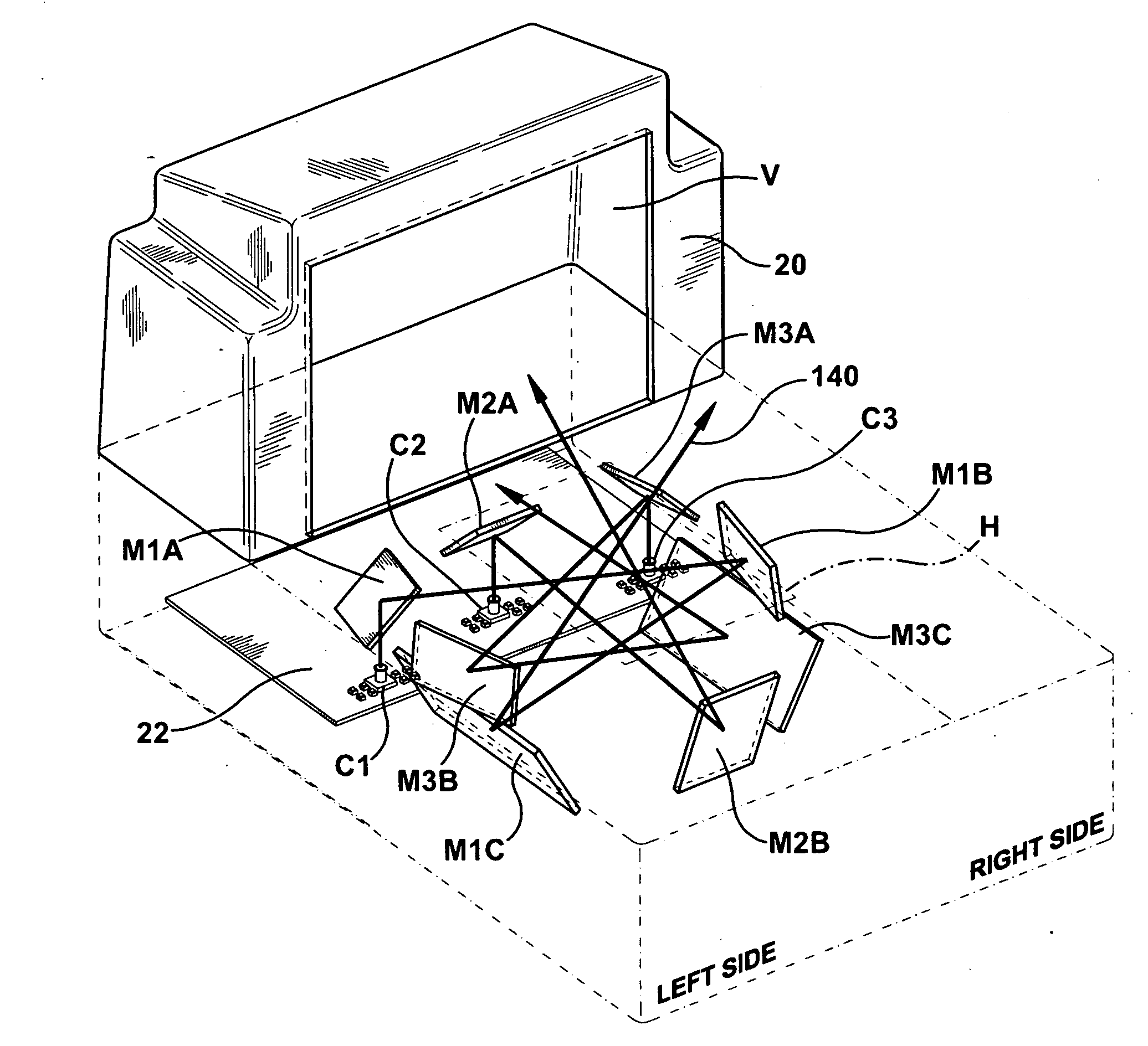
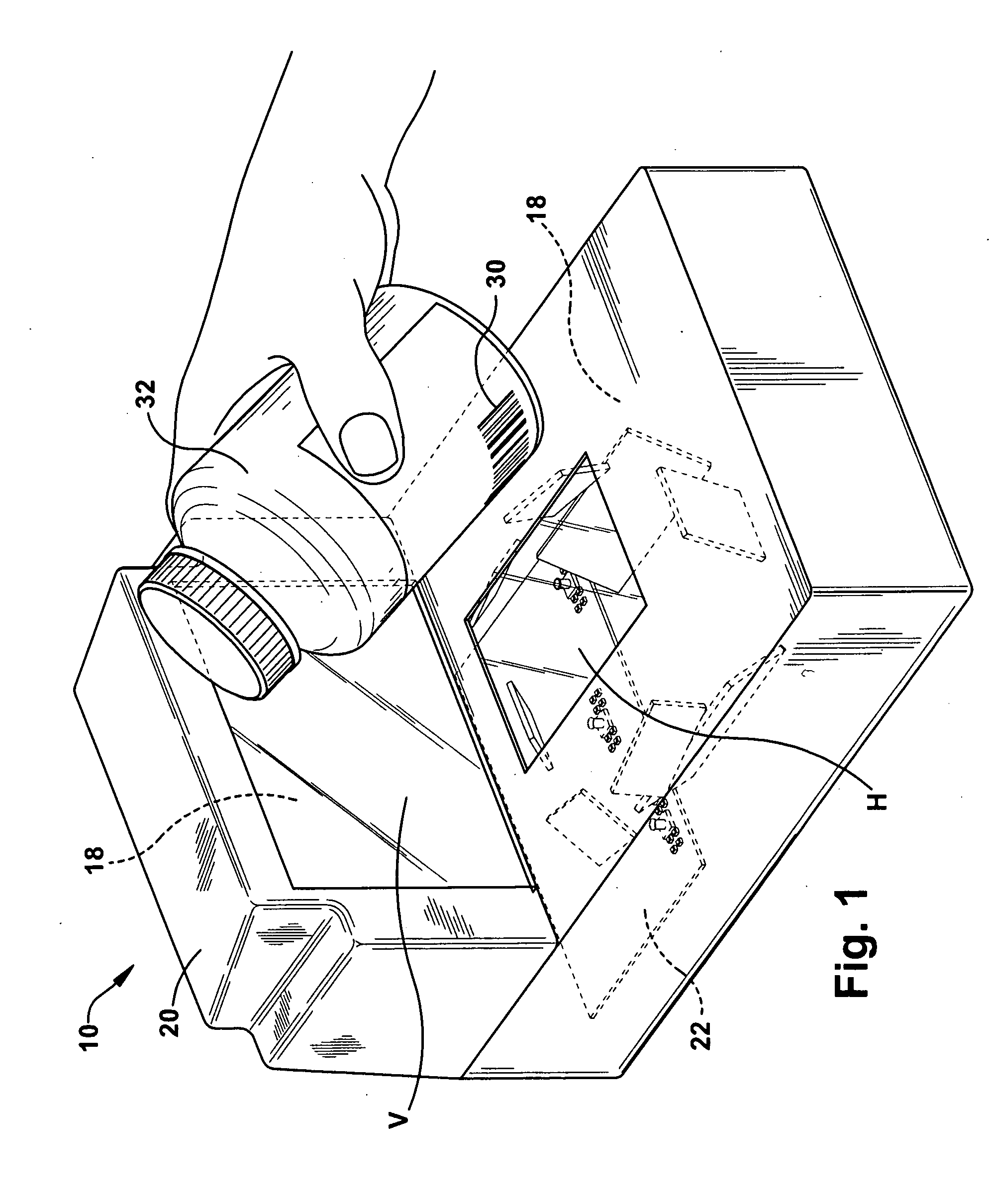
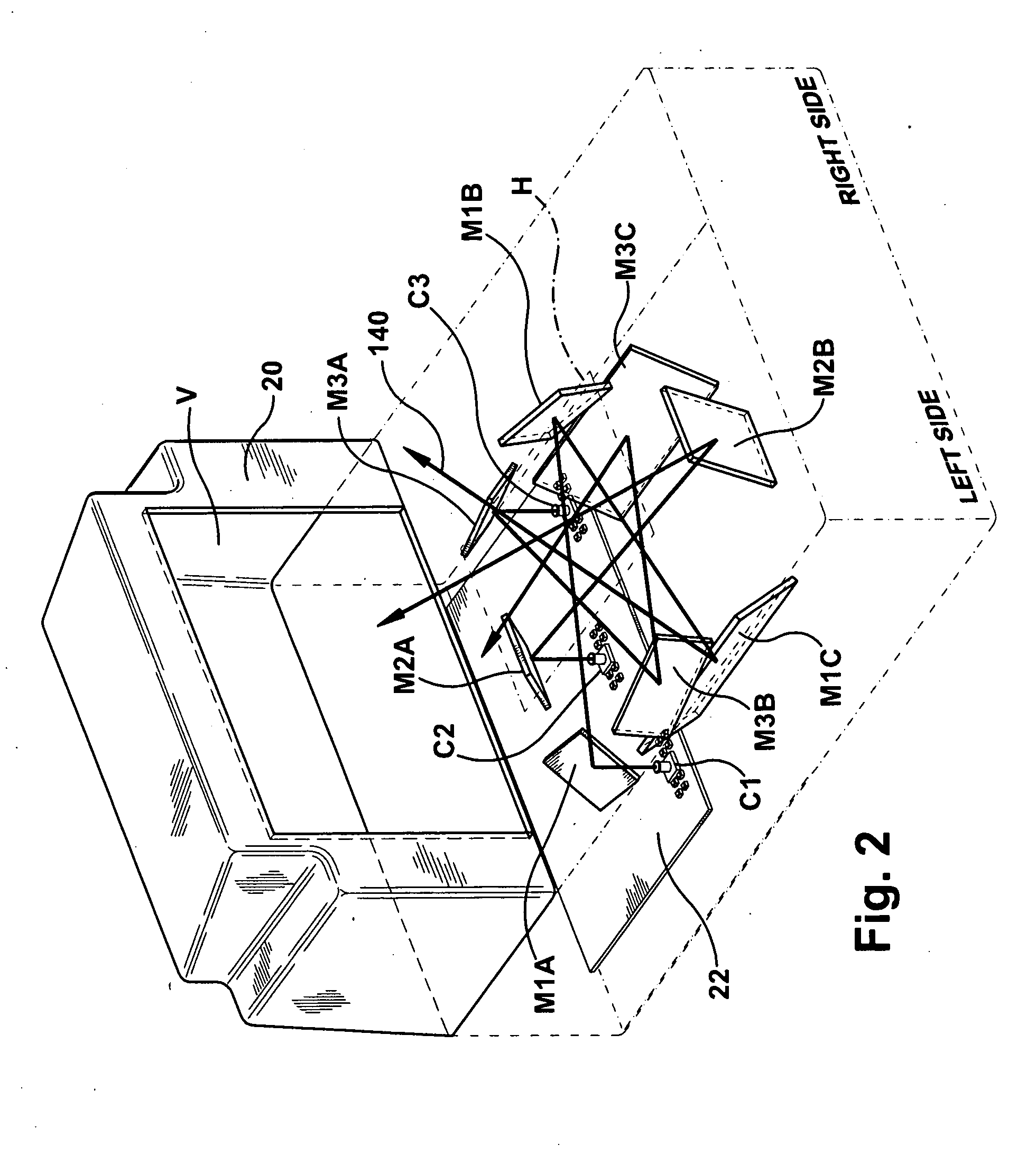
[0023]FIG. 1 depicts a stationary bar code reader 10 having an imaging and decoding system supported within an interior region 18 of a housing 20. The housing 20 may be integrated into a sales counter of a point of sales system that includes, for example, a cash register, a touch screen visual display or other type user interface and a printer for generating sales receipts. The housing 20 depicted in FIG. 1 includes two transparent windows H, V so that objects moved past the housing can be imaged.

[0024]In accordance with one use, either a sales person or a customer will swipe a product or target object 32 selected for purchase relative to the housing 20. A target bar code 30 imprinted or affixed to the target object 32 is swiped through a region near the windows H, V for reading, that is, imaging and decoding of the coded indicia of the target bar code.

Imaging Optics

[0025]An exemplary imaging system 12 has six cameras C1-C6 that capture a series of image frames in a programmable way...


PUM


Abstract

A bar code reader 10 includes a housing 20 including one or more transparent windows H, V and defining a housing interior region. As a target object is swiped or presented in relation to the transparent windows an image of the target object is captured. Cameras C1-C6 have an image capture sensor array with a global shutter is positioned within the housing interior region for capturing an image of a bar code within a camera field of view. All the cameras produce images in a sequential manner during an image frame time period. An image processing system has a processor for decoding a bar code carried by the target object. The processing system responds to signals from a light sensor to terminate object illumination when an adequate image exposure has transpired.

Description

FIELD OF THE INVENTION[0001]The present invention relates to a bar code reader having several cameras that are positioned within a housing for viewing objects moving past one or more windows to determine the content of bar codes on the objects.BACKGROUND OF THE INVENTION[0002]A bar code is a coded pattern of graphical indicia having a series or pattern of bars and spaces of varying widths that encode information. Bar codes may be one dimensional (e.g., UPC bar code) or two dimensional (e.g., DataMatrix bar code). Systems that read, that is, image and decode bar codes employing imaging camera systems are typically referred to as imaging-based bar code readers or bar code scanners.[0003]Imaging-based bar code readers may be portable or stationary. Stationary bar code readers are mounted in a fixed position and a target object, e.g., a product package that includes a target bar code, is moved or swiped past a transparent window so the object passes through a field of view of the statio...

Claims


Application Information

Patent Timeline
Patent Type & Authority Applications(United States)
IPC IPC(8): G06K7/10
CPCG06K7/10722G06K7/10732G06K2207/1018G06K7/1096G06K7/10752
Inventor BARKAN, EDWARD D.CARLSON, BRADLEY S.DRZYMALA, MARK
Owner SYMBOL TECH LLC
Why Eureka
Try Eureka