
Imaging apparatus, imaging system and method thereof

a technology of image data and imaging apparatus, applied in the field of selective image data encoding apparatus, selective image data encoding system and method thereof, can solve the problems of inability to record some or all cameras inability to achieve continuous recording at a predetermined frame rate, and inability to achieve the effect of reducing the required storage space and bandwidth

Inactive Publication Date: 2005-01-27
SONY CORP
View PDF6 Cites 69 Cited by
  • Summary
  • Abstract
  • Description
  • Claims
  • Application Information

AI Technical Summary

Benefits of technology

[0017] An optimal surveillance system should be able to record as well as process and communicate image data from related cameras at the best quality as possible, for example, 30 frames per second. However, due to technical limitations and budget restrictions in actual systems, the amount of image data that can be recorded or transmitted at a given time or in the long run is limited. For example, a maximum frame rate supported by a capture card limits the amount of image data, typically video data, which can be recorded or encoded at a given time. Limitations in storage capacity, such as disk space, limit the amount of image data that can be recorded over a longer period of time.
[0018] The apparatus, system and method according to the preferred embodiments of the present invention aims at alleviating the above problems as it is proposed to select what camera should be allocated a larger amount of frame rates in response to alarm situations detected by detectors or sensors. In other words, according to the preferred embodiments of the present invention, there is proposed an apparatus, a system and a method that permit realize selection of which camera's image data to record within the system and at what frame rate, at what moment and for how long. Given the proper inputs, the apparatus and system according to the present invention are able to calculate the required (for example, the minimum) frame rates for the cameras.
[0020] Also, the system, apparatus and method according to the preferred embodiments of the present invention as described above permit the installer of the system or the user to dynamically and flexibly configure and setup the security system so that the specific requirements or restrictions of the environment can be taken into consideration. As a result, it becomes possible to realize an optimum utilization of the available image capturing and or data processing resources.
[0021] For example, upon enabling selective allocation of frame rates according to the detector or sensor that has been activated, it becomes possible to obtain an increased amount of information related to the causes or events that caused the alarm, while for non-related images of other imaging devices it suffices not to capture any image at all or to capture images with reduced frame rate.
[0023] By optimizing the utilization of the resources of the system, it is possible to reduce the required storage space and bandwidth for performing the same process.
[0024] Also, it is possible to have more reliable pre-alarm video / image data as the system may be set so as to record such image data previous to the occurrence of the alarm with an allocation of a higher frame rate for the concerning or related imaging devices (cameras).

Problems solved by technology

However, conventional approaches for specifying frame rates for each camera in a system or specifying time intervals for recording result in sub-optimal and frequently inappropriate performance, especially where alarm sequences (more than one alarm is activated, consecutively) are considered in monitoring or surveillance systems.
Moreover, as far as limitations in memory capacity, storage space in disks and other media, as well as limitations in bandwidth of communication channels are concerned, continuous recording of some or all cameras at a predetermined frame rate is neither feasible nor practical.

Method used


Image

  • Imaging apparatus, imaging system and method thereof
  • Imaging apparatus, imaging system and method thereof
  • Imaging apparatus, imaging system and method thereof

Examples


Embodiment Construction

[0042] Preferred embodiments of the present invention are described below with reference to the attached drawings.

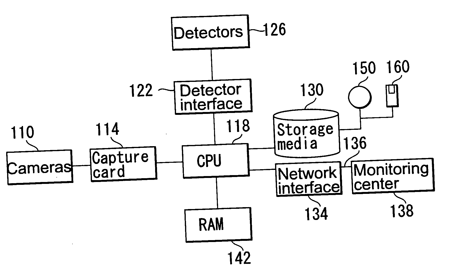
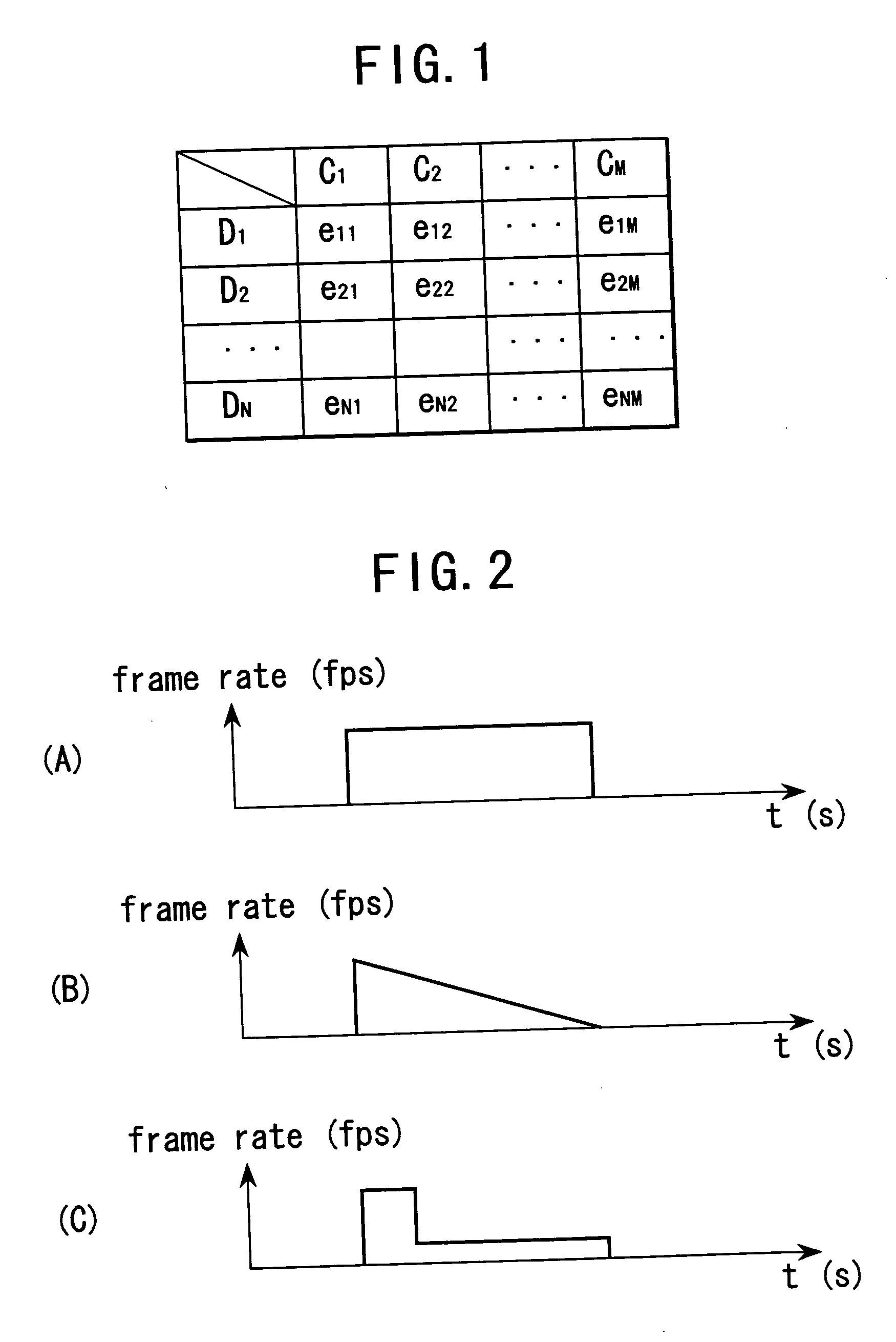
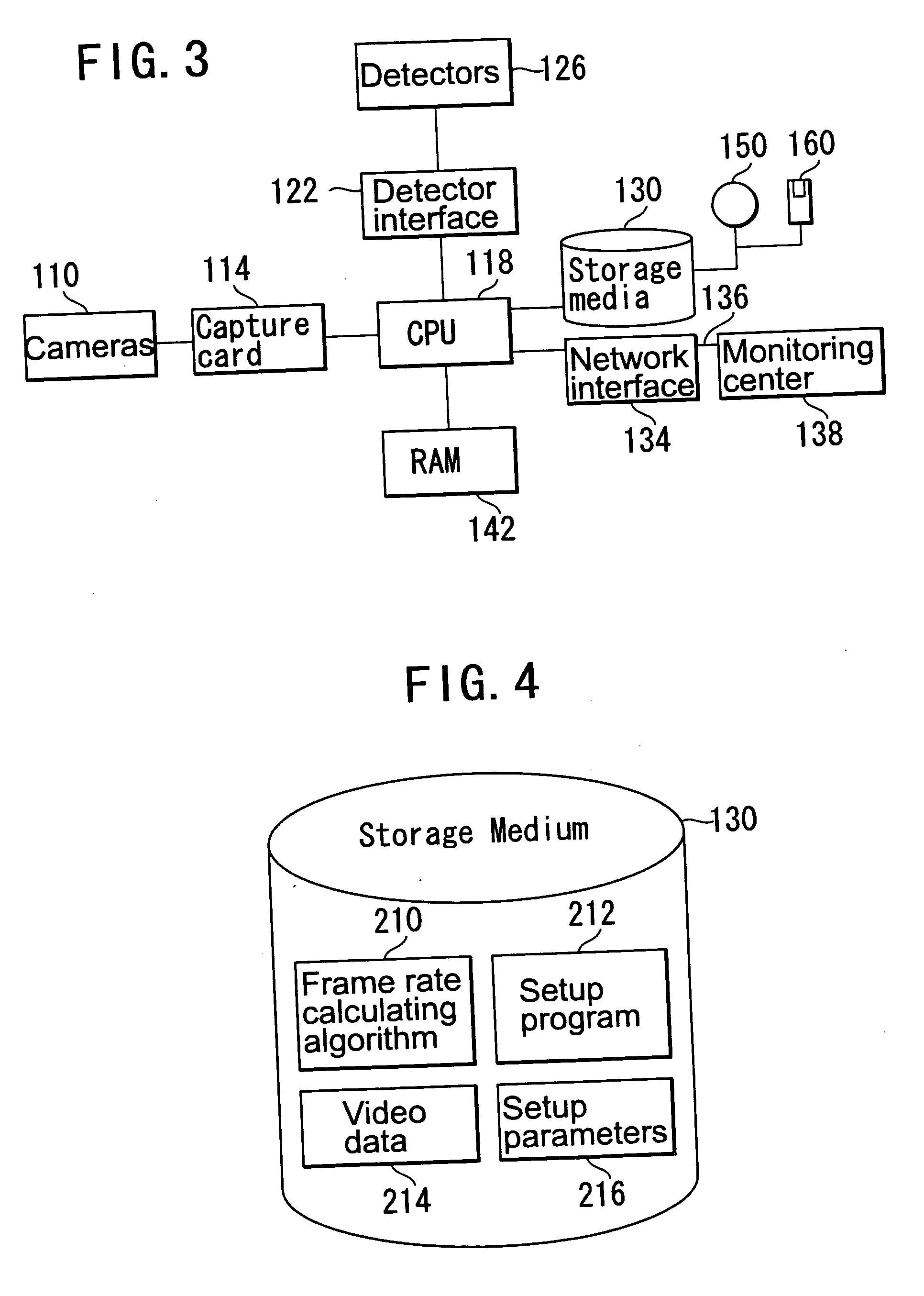
[0043]FIG. 1 shows a table illustrating an assignment of frame rates for imaging devices such as cameras in a system having a plurality of M cameras C1 to CM depending on input originated from N detectors D1 to DN. Such detectors may be disposed in a residence for surveillance for security purposes, for example. The system may also include a central processing unit (CPU), a storage medium and a random access memory (RAM). Interconnection or intercommunication between these functional units or devices will be described in more detailed below.

[0044] The storage medium serves the purpose of storing data related to settings of the system, image data related to images captured by the imaging devices (cameras), data related to signals from the detectors, etc. In addition, the storage medium may include data related to a logical association between the detectors and the imagi...


PUM


Abstract

To provide a system, apparatus and method of changing frame rate of cameras according to the detector that has sent an alarm signal, in order to optimize utilization of hardware resources. An apparatus for setting a frame rate under which images are captured by a camera in an image capturing system having a plurality of cameras and a plurality of detectors, the apparatus including: detector interface for receiving a first signal from at least one of the sensors; association unit for associating the first signal with information related to the camera; calculation unit for calculating a frame rate of each of the plurality of cameras based on the association between the first signal and the information related to the cameras; setting unit for setting the frame rate of the camera calculation by the calculation unit; and second reception unit (capture card) for receiving image data from the camera at a frame rate set by the setting unit.

Description

CROSS REFERENCE TO RELATED APPLICATIONS [0001] The present document is based on Japanese Priority Application JP2003-277765 filed to the Japanese Patent Office on Jul. 22, 2003, the contents in which being incorporated herein by reference to the extent permitted by law. BACKGROUND OF THE INVENTION [0002] 1. Field of the Invention [0003] The present invention relates to a selective image data encoding apparatus, a selective image data encoding system and method thereof. More specifically, the present invention relates to an apparatus, a system and a method for changing frame rate by which image data from an imaging apparatus is acquired and transmitted or stored in a recording medium according to a setting performed for association of sensor with imaging device. The present invention is also related to a method for setting up the settings for sensor-imaging device association for such apparatus and system. [0004] 2. Related Art [0005] Video capture cards and digital video recorders (...

Claims


Application Information

Patent Timeline
Patent Type & Authority Applications(United States)
IPC IPC(8): H04N5/232H04N5/915H04N7/18
CPCH04N7/181H04N5/232H04N23/661
Inventor FALK, DIETRICH
Owner SONY CORP
Learn More