
System and method for controlling platform mounted devices

a platform mounted device and control system technology, applied in the field of platform mounted devices, can solve the problems of power consumption of devices, limited known methods, and requiring illumination units

Active Publication Date: 2019-08-13
ITL OPTRONICS +1
View PDF11 Cites 0 Cited by
  • Summary
  • Abstract
  • Description
  • Claims
  • Application Information

AI Technical Summary

Benefits of technology

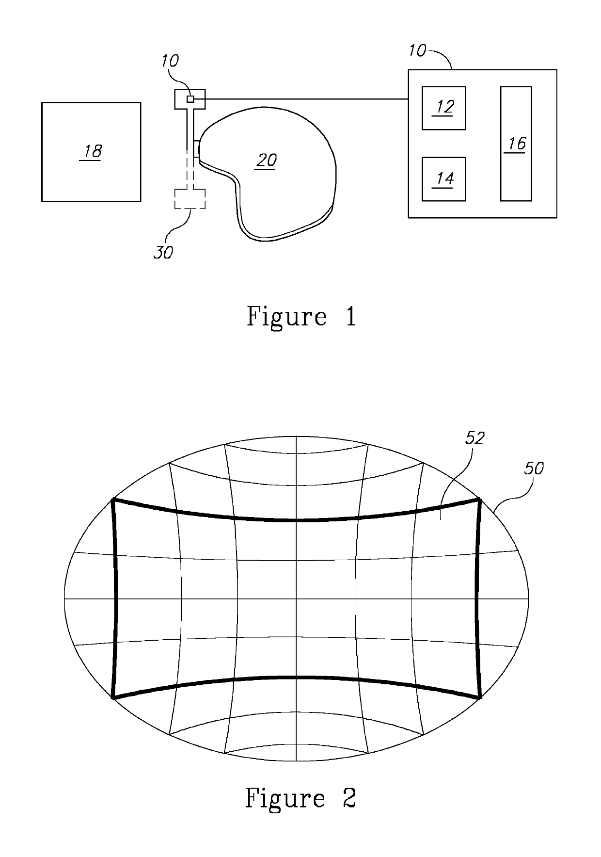
The present invention provides a system for controlling a platform mounted device that includes an orientation sensor and a processor. The orientation sensor senses the orientation of the platform mounted device relative to a horizon, such as an earth leveled frame of reference. The processor analyzes the orientation and decides whether the device is within a pre-decided portion of a sector. The processor then generates a control command based on this decision. The system can control the device by sending the generated command to a controller or actuator of the head mounted device. The indication module can generate an indication to a user based on the control command. The technical effects include improved control and accuracy for platform mounted devices.

Problems solved by technology

Usually, such devices consume power and require illumination units to illuminate the environment in front of a user such as, for example, a soldier carrying the device.
However, most of the known methods are limited to certain mechanical arrangement of the device and to a certain manner of connection of the device.
Particularly, most of the known methods are limited to devices that may vertically tilt up or down, above the user's field of view or into the user's field of view, respectively.
None of the known methods may detect location and orientation of a device with illuminating capabilities relative to a platform regardless the certain mechanical arrangement of the device or manner of connection of the device to the platform.

Method used


Image

  • System and method for controlling platform mounted devices
  • System and method for controlling platform mounted devices
  • System and method for controlling platform mounted devices

Examples


Embodiment Construction

[0022]In the following detailed description, numerous specific details are set forth in order to provide a thorough understanding of the invention. However, it will be understood by those skilled in the art that the present invention may be practiced without these specific details. In other instances, well-known methods, procedures, and components have not been described in detail so as not to obscure the present invention.

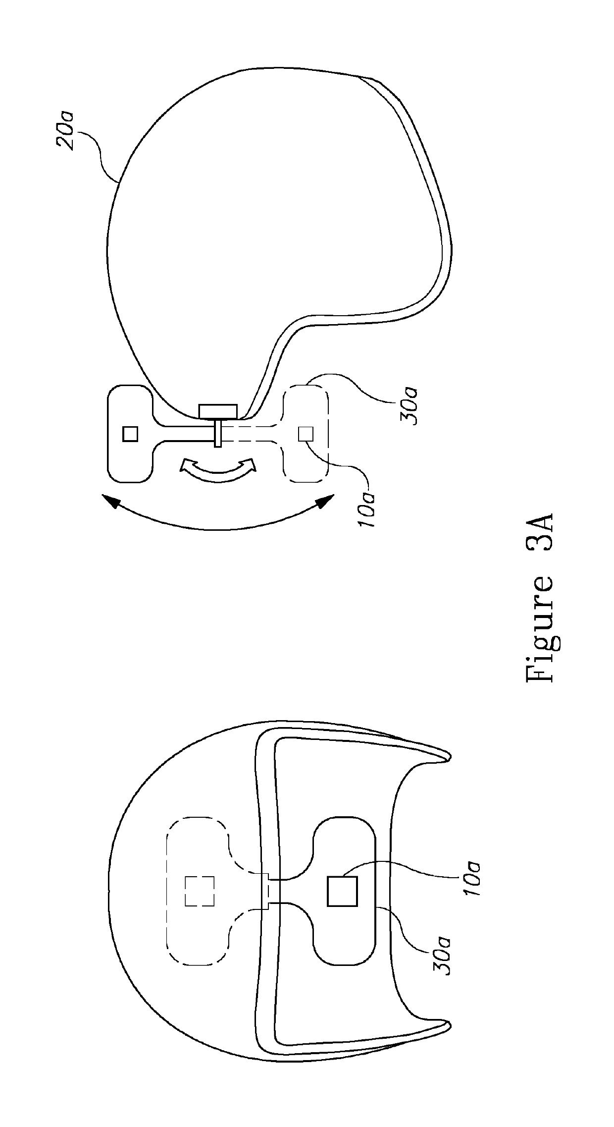
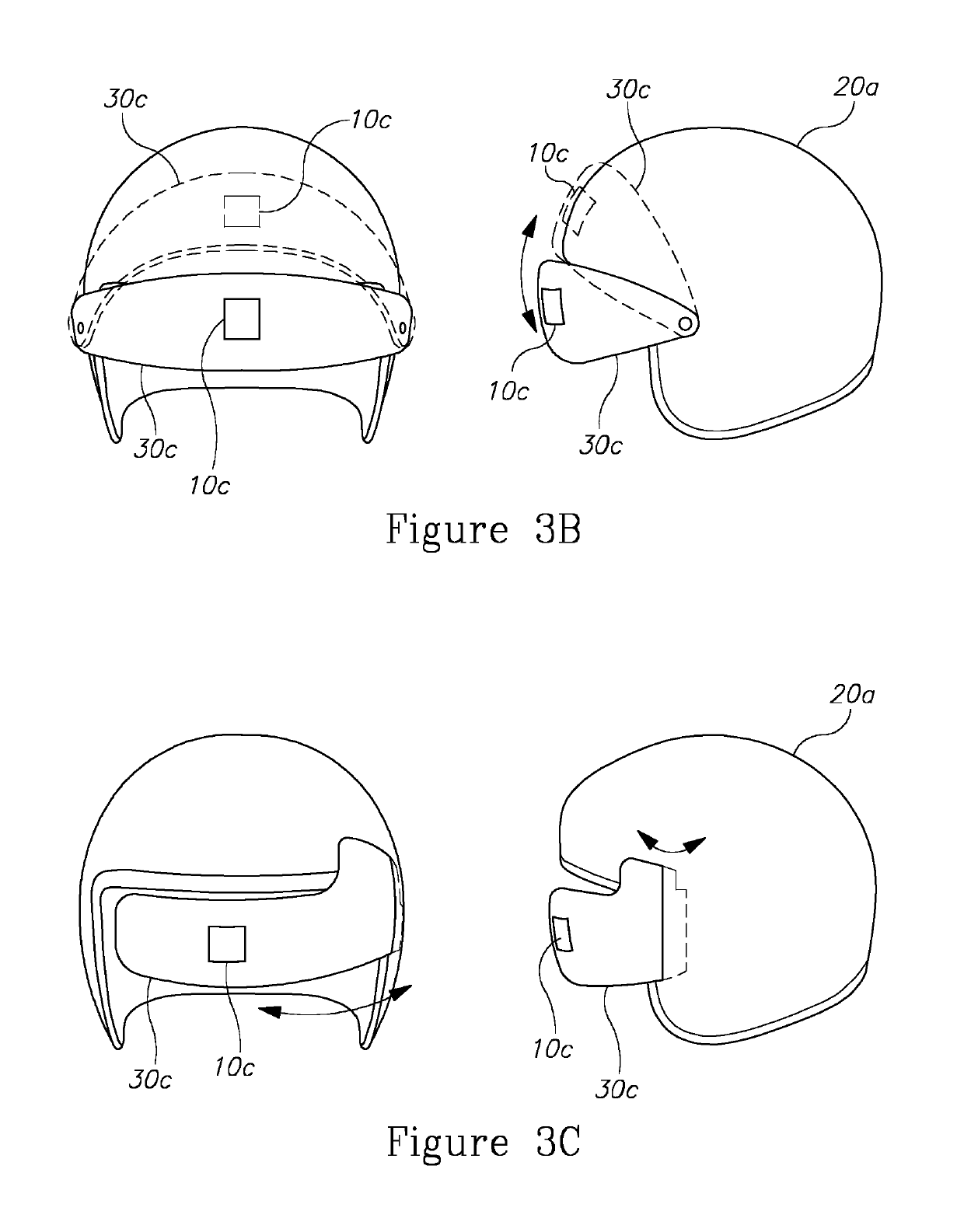
[0023]The present invention, in embodiments thereof, provides a system for controlling a platform mounted devices. Platform mounted devices, for the purpose of the embodiments of the present invention may include laser systems, optical markers, hand held devices, head mounted devices, firearm sights and any active device that is attached to a platform and may change its orientation relative to the platform. Embodiments of the present invention are configured to alter the operative state of the platform mounted device in a predefined geometric sector that correspon...


PUM


Abstract

A system for controlling a platform mounted devices which includes an orientation sensor configured to sense orientation of the platform mounted device relative to an earth leveled frame of reference; and a processor configured to: create a sector relative to the earth leveled frame of reference, receive from said orientation sensor an indication about orientation of said mounted device, analyze orientation versus the created sector, decide whether the device is within a pre-decided portion of the sector, and generate a control command according to the decision.

Description

CROSS-REFERENCE TO RELATED APPLICATIONS[0001]This application is a National Phase Application of PCT International Application No. PCT / IL2014 / 050502, International Filing Date Jun. 3, 2014, entitled “SYSTEM AND METHOD FOR CONTROLLING PLATFORM MOUNTED DEVICES”, published on Dec. 11, 2014 as International Patent Application Publication No. WO 2014 / 195947, claiming priority of Israel Patent Application No. 226701, filed Jun. 3, 2013, which is incorporated herein by reference in its entirety.FIELD OF THE INVENTION[0002]The present invention relates generally to platform mounted devices, and more particularly, to such devices whose operation is controlled with respect to their orientation.BACKGROUND OF THE INVENTION[0003]Platform mount devices such as night vision goggles or other vision improvement tools are used for military and / or security missions. Usually, such devices consume power and require illumination units to illuminate the environment in front of a user such as, for example,...

Claims


Application Information

Patent Timeline
Patent Type & Authority Patents(United States)
IPC IPC(8): G02B27/01G05B15/02
CPCG02B27/0176G02B27/017G05B15/02G02B2027/0163G02B2027/0156
Inventor MALKA, YITZHAK
Owner ITL OPTRONICS
Learn More