
Barrel shaft for a clock movement, barrel spring, and barrel including such a spring and/or such a shaft

Active Publication Date: 2019-09-03
ROLEX SA
View PDF32 Cites 0 Cited by
  • Summary
  • Abstract
  • Description
  • Claims
  • Application Information

AI Technical Summary

Benefits of technology

The invention proposes a barrel shaft that can be fixed reliably, industrial and demountably, without severe deformation of the springs. It also allows for a smaller core diameter without needing to modify the standard arrangement of the barrel.

Problems solved by technology

This solution leads to high mechanical deformation of the end of the barrel spring, which is not the optimum.
This type of attachment with no mechanical connection is a priori relatively unreliable.
This solution also leads to high mechanical deformation of the end of the spring, which is not the optimum.
Thus there is no known solution for fastening a barrel spring to a barrel shaft reliably, industrially, demountably and without severe plastic deformation of the spring and providing the possibility of minimizing the core diameter without having to modify the standard arrangement of the barrel, and in particular the pivoting of the drum and the cover on the shaft.
The teachings of that document are not applicable to the problem of a clock barrel spring.
In fact, with the barrel described in the above document it is not possible to maximize the space available for the spring and the construction used cannot be employed to produce a barrel with its cover and its drum, for the following reasons:The document gives no indication concerning the placement of the drum and the cover, which must be able to pivot on the shaft.
A traditional construction can therefore not be obtained based on the solution described in the document.Additionally, this type of construction does not enable the user to wind the barrel while the camera is operating, which is a fundamental requirement for a clock barrel.

Method used


Image

  • Barrel shaft for a clock movement, barrel spring, and barrel including such a spring and/or such a shaft
  • Barrel shaft for a clock movement, barrel spring, and barrel including such a spring and/or such a shaft
  • Barrel shaft for a clock movement, barrel spring, and barrel including such a spring and/or such a shaft

Examples


first embodiment

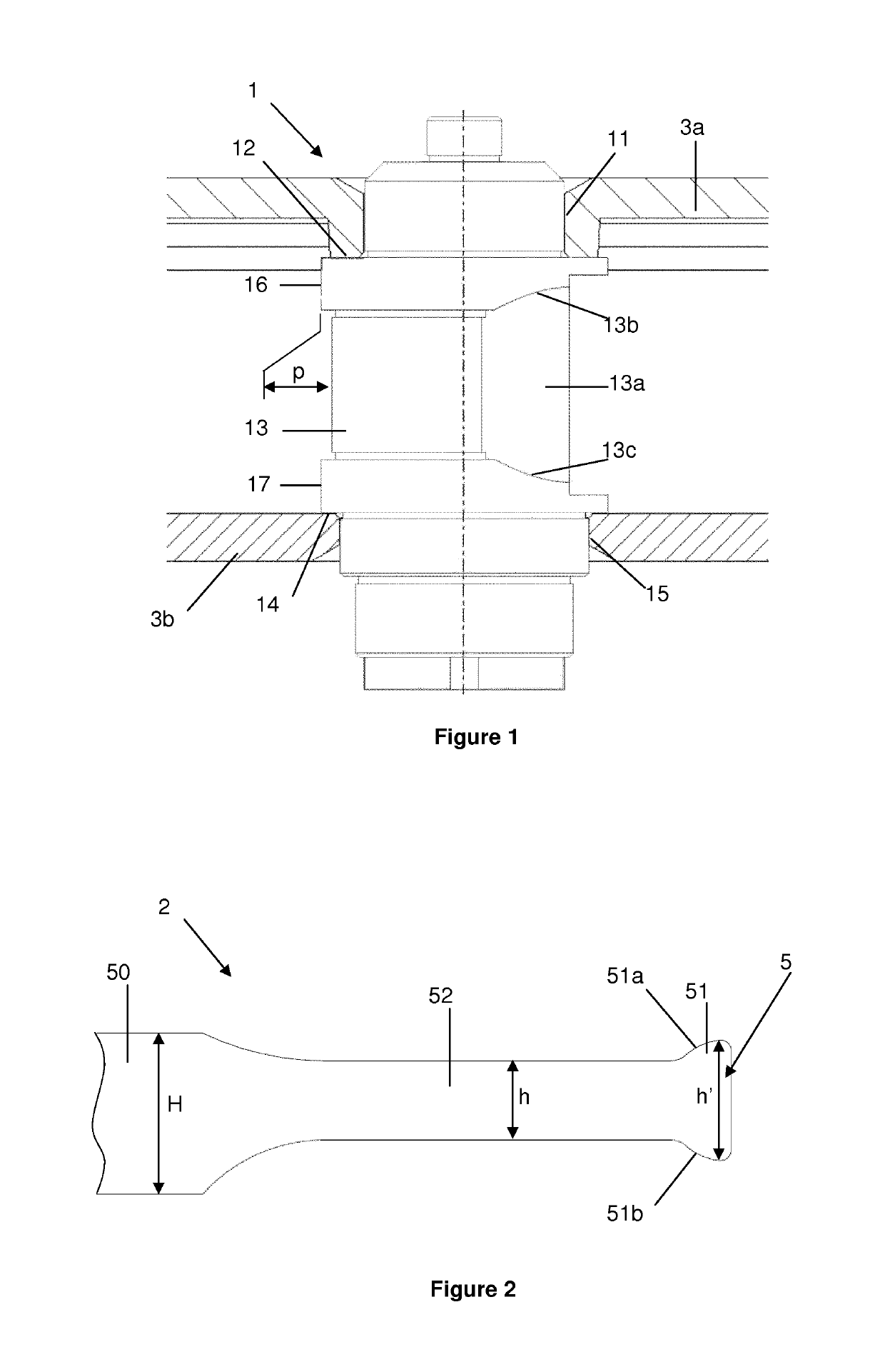
[0050]a barrel 4 according to the invention is described hereinafter with reference to FIGS. 1 to 3. The barrel primarily comprises a barrel shaft 1, a barrel spring 2, a barrel drum 3a and a barrel cover 3b (which is not represented in FIG. 3).

[0051]The drum barrel includes teeth for driving the wheels of a clock mechanism, notably a wristwatch mechanism. The barrel stores the mechanical energy necessary for the clock mechanism to operate. This energy is stored in the form of elastic potential energy, because of the deformation of the spring. Indeed, the spring is a blade spring coiled up round the shaft inside the drum, the spring being mechanically connected to the shaft at its interior end 5 and mechanically connected to the drum at its exterior end. When the spring is completely wound, it is coiled up on the shaft and is able to drive rotation of the drum relative to the shaft. The spring is represented in the unwound state in FIG. 3, the spring being coiled up on itself inside...

second embodiment

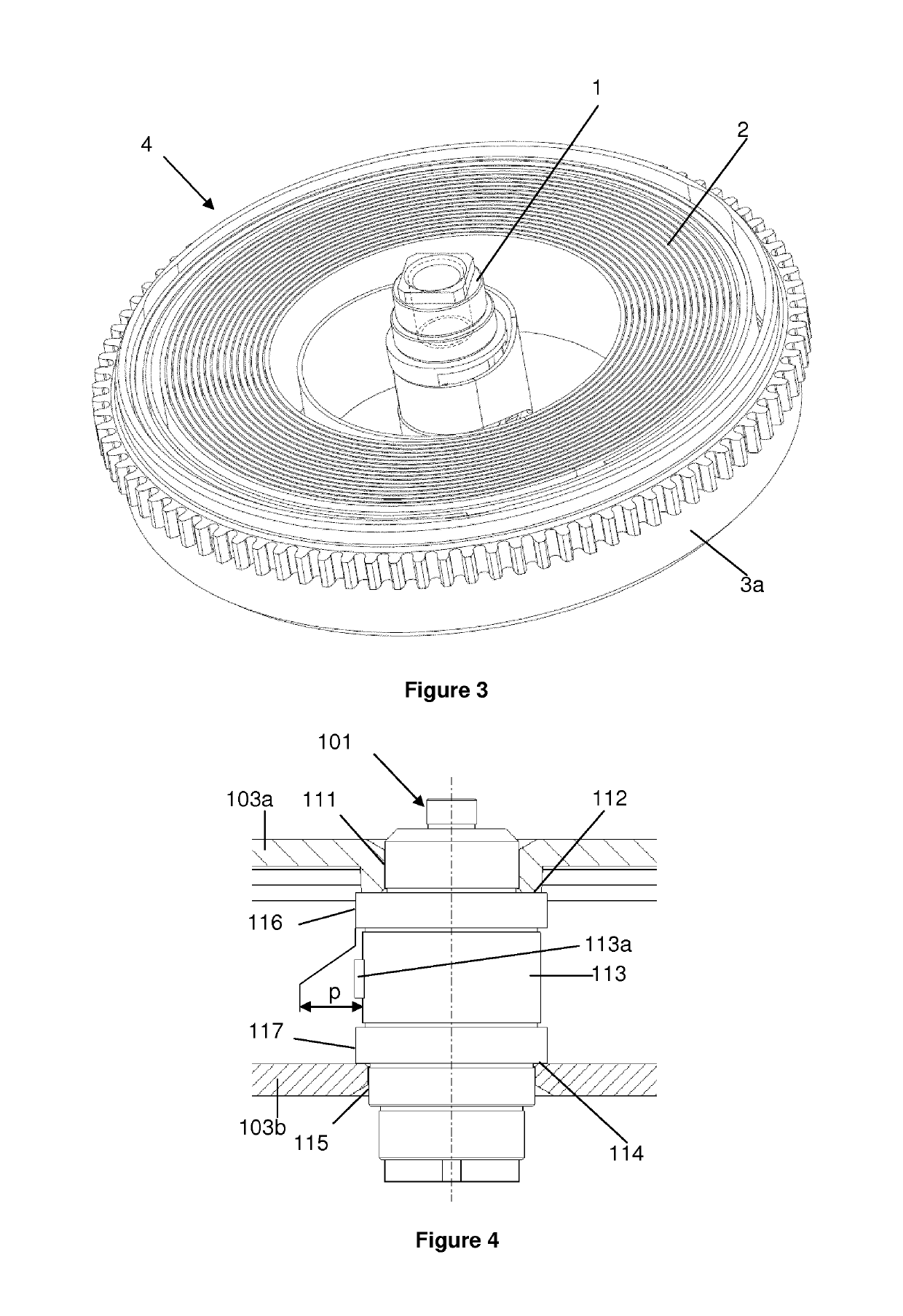
[0075]In the second embodiment, a catch or hook 113a is produced on the shaft at the bottom of the groove 113. Production of such a catch or hook is relatively complicated.

[0076]The catch or the hook cooperates with an opening (“pigeonneau” in French) 151 produced at the end 105 of the spring. The opening is substantially rectangular, for example. The catch or the hook is conformed to be inserted in this opening.

[0077]The shaft pivots in a jewel bearing at its upper end. As represented in FIG. 4, the drum 103a for its part pivots on the shaft at the level of the portion 111 and the bearing surface 112, while the cover 103b does likewise on the portion 115 and the bearing surface 114.

[0078]A third embodiment of a barrel shaft according to the invention and a third embodiment of a barrel spring according to the invention are described hereinafter with reference to FIGS. 6 and 7.

[0079]In the illustration of this third embodiment, elements that are identical or similar to or have the sa...

third embodiment

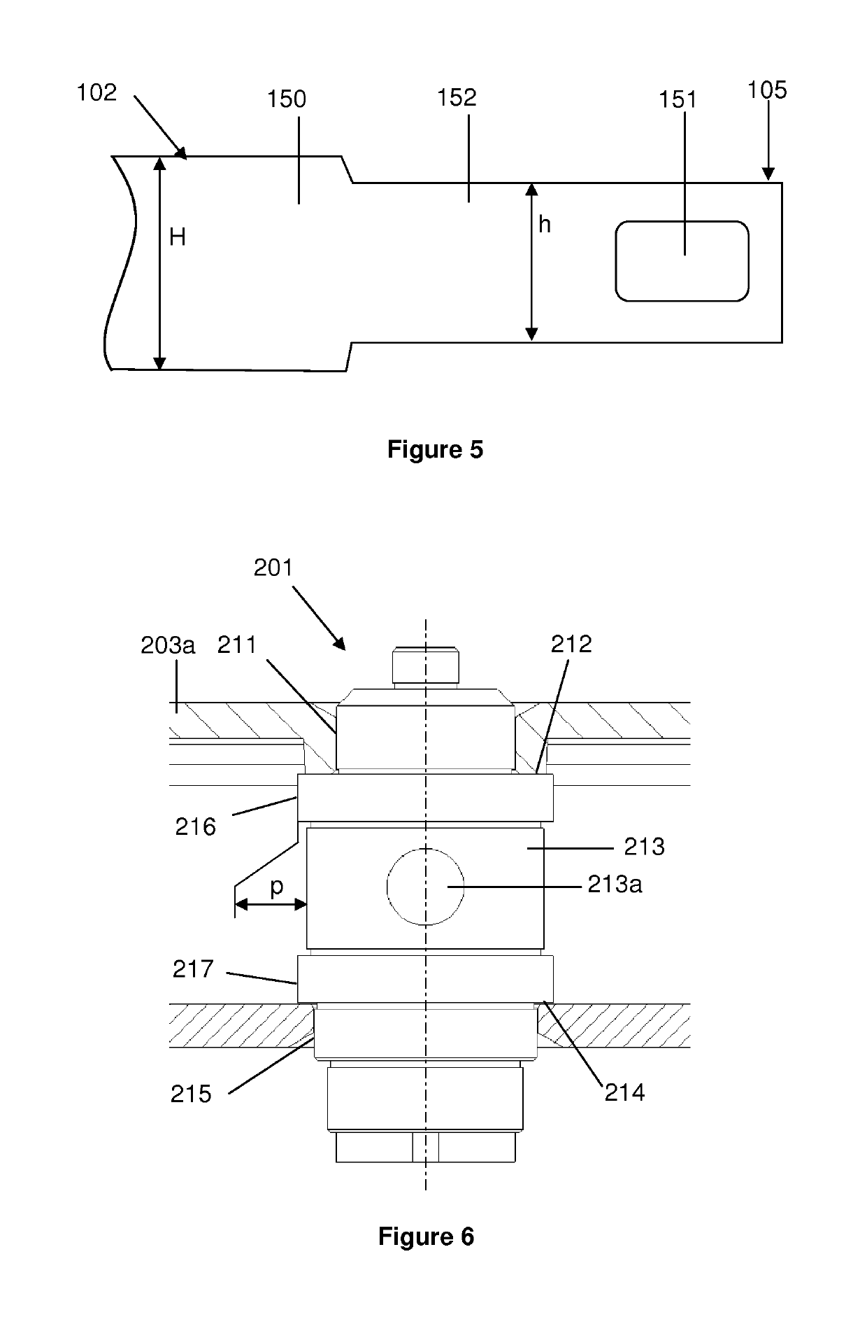
[0081]In the third embodiment, a cut-out 213a is produced in the shaft at the bottom of the groove 213, for example by a bore. This cut-out is perpendicular to the axis of the shaft, for example.

[0082]The cut-out cooperates with a pin 251 fixed to the end 205 of the spring. The pin may notably be riveted to the spring.

[0083]This solution necessitates an additional component but makes it possible to simplify the production of the shaft.

[0084]A fourth embodiment of a barrel shaft according to the invention and a fourth embodiment of a barrel spring according to the invention are described hereinafter with reference FIGS. 8 and 9.

[0085]In the illustration of this fourth embodiment, elements that are identical or similar to or have the same function as those of the first embodiment have reference numbers increased by three hundred. For example, the shaft of the fourth embodiment and the spring of the fourth embodiment are referenced “301” and “302” whereas the shaft of the first embodim...


PUM


Abstract

The invention relates to a barrel spring (2) including: an inner end (5) and an outer end; a first portion (50) having a first height (H); a second portion (52) having a second height (h) that is smaller than the first height (H) and being located near the inner end (5); and, at the second portion, e.g. at the inner end, a first attachment element (51) suitable for being attached to the barrel shaft, wherein the second portion is to be inserted into a circumferentially extending groove provided on the barrel shaft.

Description

[0001]This application is a divisional of U.S. application Ser. No. 14 / 390,699 filed Oct. 3, 2014, which is a U.S. national stage of International Application No. PCT / EP2013 / 057064 filed Apr. 4, 2013, each of which claims priority of European Patent Application No. 12002440.1 filed Apr. 4, 2012, the entire contents of each of which are hereby incorporated by reference.BACKGROUND ART[0002]The invention relates to a clock movement barrel shaft or a shaft for a clock movement barrel. It also relates to a clock movement barrel spring or a spring for a clock movement barrel. It further relates to a barrel including such a shaft and / or such a spring. It finally relates to a clock movement or a timepiece, notably a wristwatch, including such a shaft and / or such a spring.[0003]The Professional Illustrated Dictionary Of Clockmaking (“Dictionnaire Professionnel Illustré de l'Horlogerie”) describes a classic construction of a barrel shaft for attaching a barrel spring. The shaft supports the d...

Claims


Application Information

Patent Timeline
IPC IPC(8): G04B1/14G04B1/18G04B1/16
CPCG04B1/18G04B1/16G04B1/14
Inventor BERTRAND, JEAN-LOUISBORTOLI, ALBERTGYGER, THOMASVON NIEDERHÄUSERN, VINCENTVON NIEDERHAUSERN, VINCENT
Owner ROLEX SA
Learn More