Methods and apparatus for balancing rotatable devices

a technology of rotatable devices and methods, applied in the direction of non-positive displacement fluid engines, pump components, liquid fuel engine components, etc., can solve the problems of impeller damage, impeller debris blockage, and inability to be used, so as to minimize the lifting distance

Active Publication Date: 2019-10-08
CONNECTING PRODS
View PDF7 Cites 0 Cited by
  • Summary
  • Abstract
  • Description
  • Claims
  • Application Information

AI Technical Summary

Benefits of technology

[0020]D) raising the elongated tool so that the pivot point contacts the workpiece, causing the workpiece to tip toward an operator and away from the distance sensors,
[0021]E) setting a lifting distance minimized and suited to the ability of the distance sensors to discern tipping,

Problems solved by technology

Therefore, at least three or four of the aforementioned components contribute to the rotational imbalance, but the final resultant imbalance is determined by the offset of the center of mass to the turning axis.
Ideally, the entire rotating assembly should be balanced, but this is usually not practical.
For example, in the case of blowers which also act as vacuums, the impeller becomes clogged with debris and requires cleaning, so it is frequently removed and reassembled.
Also, sometimes the impeller is damaged, and has to be replaced.

Method used


Image

  • Methods and apparatus for balancing rotatable devices
  • Methods and apparatus for balancing rotatable devices
  • Methods and apparatus for balancing rotatable devices

Examples


example

[0088]In accordance with one embodiment, the balancing and boring procedure may be listed stepwise as follows:

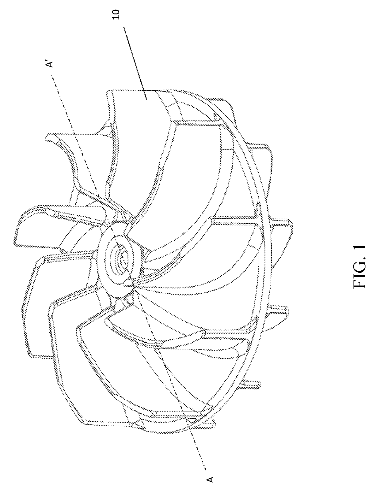
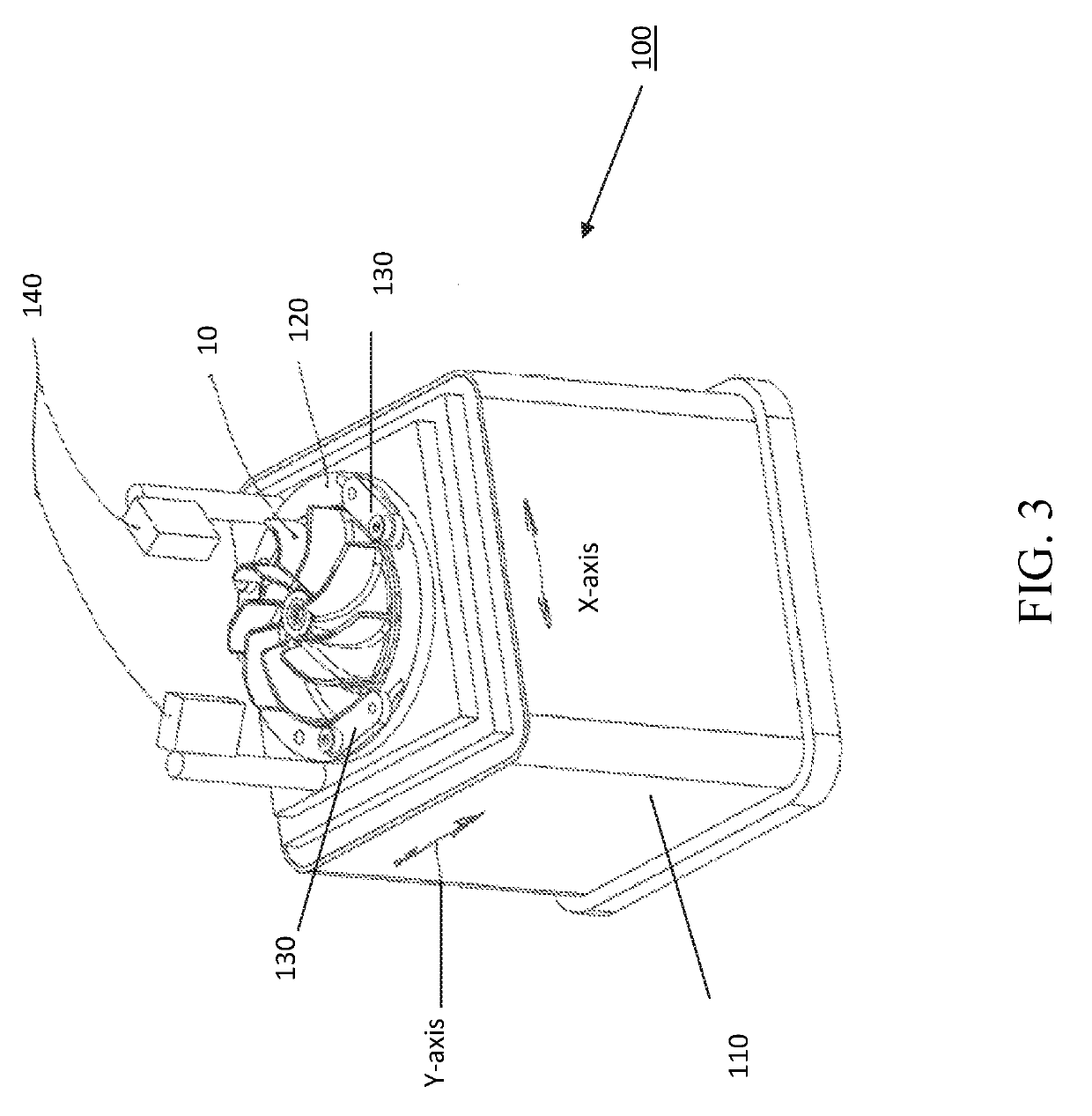
[0089]1. The workpiece 10 is placed in the holder 120.

[0090]2. The clamps are operated to centralize the workpiece 10.

[0091]3. The clamps are released.

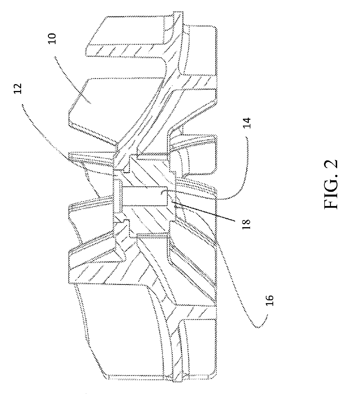
[0092]4. The tool 200 is raised so that the pivot point 203 contacts the surface 16 of workpiece 10, and lifts the workpiece 10 the distance Z. The workpiece 10 then tips at the periphery the distance Z, and settles in a stable position.

[0093]5. The sensors 140 determine how much to move the workpiece along the X-axis so that the laser measurements are equal, and the tipping direction is parallel with the Y axis.

[0094]6. The tool 200, and hence the pivot point 203, is lowered so that the pivot point 203 is not in contact with the workpiece 10.

[0095]7. The workpiece 10 is centralized and clamped.

[0096]8. The movement along the X-axis is performed.

[0097]9. The clamps are unclamped.

[0098]10. The tool 200 is raised such that the p...


PUM


Abstract

An apparatus for locating a center of gravity of a workpiece and forming a bore in the workpiece, the apparatus including a housing having a base configured to support the apparatus on a surface, a mounting plate, an X-axis plate slidably disposed on a first side of the mounting plate opposite a second, base-facing side of the mounting plate, a Y-axis plate slidably disposed on the X-axis plate, a holder coupled to the side of the Y-axis plate opposite the X-axis plate, wherein the holder is configured and operable to receive and retain the workpiece, a securing device operable to releasably secure the workpiece in the holder, at least two distance sensors positioned adjacent the holder, an elongated tool mounted within the housing axially aligned with central apertures formed in each of the mounting plate, Y-axis plate and X-axis plate, wherein the elongated tool is operable to move reciprocally and rotatably, and motors operable to move each of the Y-axis plate, X-axis plate and elongated tool.

Description

CROSS-REFERENCE TO RELATED APPLICATIONS[0001]This application claims the benefit of U.S. Provisional Patent Application No. 62 / 252,831 filed Nov. 9, 2015, the entirety of which is incorporated herein by reference.FIELD OF THE INVENTION[0002]The invention relates to rotatable devices and methods and apparatus for balancing such devices.BACKGROUND[0003]Many commercially available products such as leaf blowers, blenders, fans etc. use small motors having an impeller or propeller mounted to a rotor. Vibration in such devices can be unpleasant, and in some cases, cause injury to the operator or damage to the device itself when excessive. The vibration in such devices arises principally from rotational imbalance in the impeller or propeller assembly. For example, as the rotating assembly revolves at 15,000 rpm, any imbalance above about 0.6 gram inches causes unpleasant vibration.SUMMARY OF THE INVENTION[0004]Rotatable devices such as impellers and propellers are essential elements in app...

Claims


Application Information

Patent Timeline
Patent Type & Authority Patents(United States)
IPC IPC(8): F04D29/00F04D29/66F04D29/28F04D29/22
CPCF04D29/669F04D29/281F04D29/22F04D29/662
Inventor FREAKES, ANTHONY
Owner CONNECTING PRODS
Why Eureka
Try Eureka