
Method for determining imbalance in a vector signal modulator

Inactive Publication Date: 2007-02-20
AGILENT TECH INC
View PDF5 Cites 12 Cited by
  • Summary
  • Abstract
  • Description
  • Claims
  • Application Information

AI Technical Summary

Benefits of technology

[0012]Other embodiments of the present invention substantially correct the measured imbalance in the vector signal modulator by applying an inverse of a function of the imbalance(s) to the vector signal modulator.
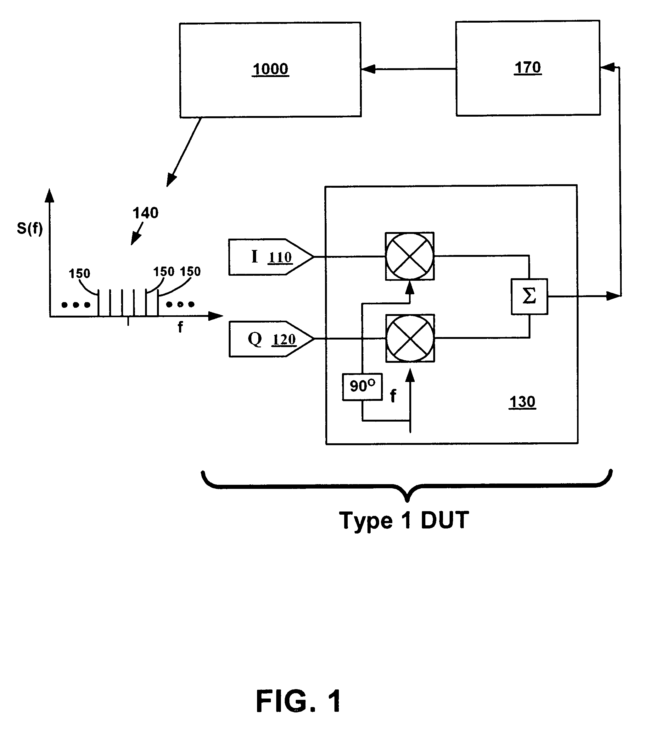
[0014]In performing the above, embodiments of the present invention provide for a method of determining amplitude and phase imbalance in a vector signal modulator. Embodiments quickly and accurately measure an output of the vector signal modulator while stimulating the vector signal modulator in a similar fashion as would actual communication signals that would typically be used in the vector signal modulator.

Problems solved by technology

This imbalance may be an amplitude imbalance.
This imbalance may be a phase imbalance.
Output measurements are then made and imbalances are calculated.

Method used


Image

  • Method for determining imbalance in a vector signal modulator
  • Method for determining imbalance in a vector signal modulator
  • Method for determining imbalance in a vector signal modulator

Examples


Embodiment Construction

[0026]In the following detailed description of embodiments of the present invention, a method of determining amplitude and phase imbalance in a vector signal modulator, numerous specific details are set forth in order to provide a thorough understanding of embodiments of the present invention. However, embodiments of the present invention may be practiced without these specific details or by using alternative elements or methods. In other instances well known methods, procedures, components, and circuits have not been described in detail as not to unnecessarily obscure aspects of embodiments of the present invention.

Notation and Nomenclature

[0027]Some portions of the detailed descriptions that follow are presented in terms of procedures, logic blocks, processing, and other symbolic representations of operations on data bits within a computer memory. These descriptions and representations are the means used by those skilled in the data processing arts to most effectively convey the s...


PUM


Abstract

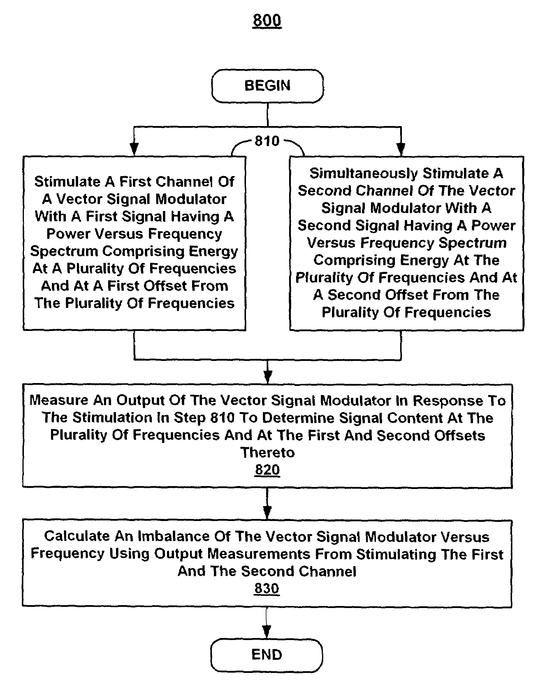
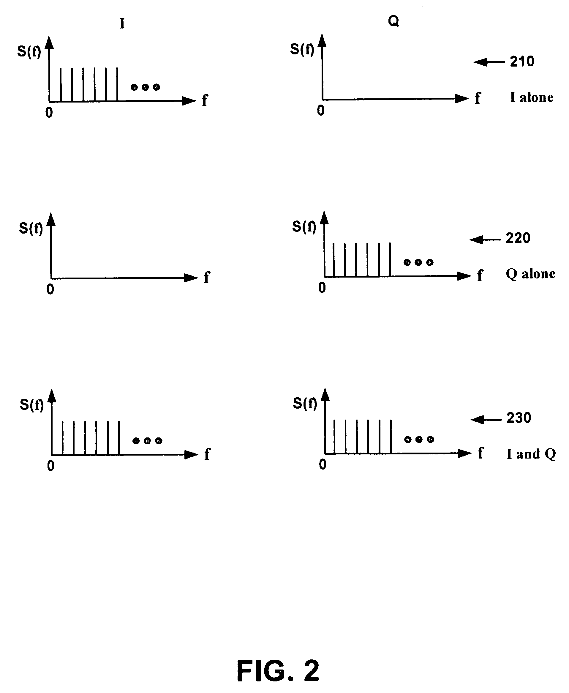
A method of determining imbalance in a vector signal modulator. First and second channels of a vector signal modulator are stimulated with a multi-tone signal having a power versus frequency spectrum having numerous of frequencies. In response to the stimulation, an output of the vector signal modulator is measured. The first and second channels are simultaneously stimulated with a multi-tone signal having essentially the same characteristics as the one used when separately stimulating the channels. Data collected from both the separate and simultaneous stimulations are used to calculate imbalance versus frequency of the vector signal modulator. Alternatively, two channels of a vector signal modulator are simultaneously stimulated with first and second multi-tone signals. The first and second multi-tone signals have tones at main frequencies and at first and second offsets thereto, respectively. Output measurements are then made and imbalances are calculated.

Description

TECHNICAL FIELD[0001]Embodiments of the present invention relate to the field of digital communications systems. Specifically, embodiments of the present invention relate to a method of measuring amplitude and phase imbalance in a vector signal modulator.BACKGROUND ART[0002]Vector modulation or I / Q modulation is a method of modulating a carrier with two baseband signals, referred to as the I (in-phase) and Q (quadrature-phase) components. Use of such modulation allows for an efficient and accurate means of transmitting information on a modulated carrier wave. A typical transmitter may have two baseband sources, one for the I channel and one for Q channel.[0003]Ideally, the I channel and Q channel will have exactly the same gain across all frequencies of interest. Moreover, in quadrature modulation the Q channel should be exactly 90 degrees out of phase with the I channel across all frequencies of interest. However, due to problems such as component mismatches and design flaws, there...

Claims


Application Information

Patent Timeline
IPC IPC(8): H04B3/46H04B1/04H04B17/00H04B7/00H04Q1/20H04L27/00H04L27/26H04L27/36
CPCH04L27/364H04L27/2626H04L2027/0024
Inventor MATRECI, ROBERT J.SPOTTED-ELK, ERIC N.THYSELL, PETER A.
Owner AGILENT TECH INC
Learn More