Supercharge Your Innovation With Domain-Expert AI Agents!

Thermal probe

a probe and probe tip technology, applied in the field of thermometers, can solve the problems of difficult control of the close distance between the probe tip and sample interface, interference with thermal measurement, and increase in radiation heat transfer with decreasing gap size, etc., to achieve the effect of improving the thermal probe for scanning thermal microscope, reducing the bending, and reducing the bending

Inactive Publication Date: 2019-11-05
NEDERLANDSE ORG VOOR TOEGEPAST NATUURWETENSCHAPPELIJK ONDERZOEK TNO
View PDF5 Cites 0 Cited by
  • Summary
  • Abstract
  • Description
  • Claims
  • Application Information

AI Technical Summary

Benefits of technology

[0008]Advantageously, a force on the probe tip along the probe direction, causes minimal or no bending of the cantilever strip as configured herein because the cantilever strip in unbended state lies in-plane with the probe tip. Accordingly, a curvature of the cantilever strip is less affected by surface forces. Preferably, the thermal conducting body experiences minimal or no bending under the influence of temperature variation. For example the thermal conducting body consists of a single material or combination of materials having substantially the same or similar heat expansion coefficient. As a result, the bending of the probe frame holding the probe tip can be largely independent of the bending of the cantilever strip because the probe frame does not bend under thermal influence like the cantilever strip. Accordingly, a position of the probe tip is less affected by thermal influence. In view of these and other advantages described below, an improved thermal probe for a scanning thermal microscope is obtained.
[0009]By supporting the tip of the thermal probe over the sample interface using one or more support arms consisting of a single material, the tip can be held more stably over the sample interface. For example, the bi-material cantilever strip can be arranged between two support arms of a single material. By configuring the cantilever strip to bend in a direction parallel to the plane of the sample interface, the curvature of the strip can be less dependent on movement of the probe in the direction of the tip, which is perpendicular to the sample interface. Accordingly, measurement accuracy can be further improved. For example, the cantilever strip can be extended sideways from the probe frame, perpendicular to the probe direction.
[0010]By providing distance between the probe tip and the cantilever strip with at least part of the single-material probe frame there between, movement of the tip can be further decoupled from movement of the cantilever. Decoupling can be further improved by providing a probe frame with increased rigidity with respect to the cantilever strip. In one embodiment, the layers of the bi-material cantilever strip have a combined thickness that is lower than a thickness of the single-material layer of the probe frame. Alternatively or additionally, a relatively low rigidity of the cantilever strip can be provided by the choice of less rigid materials.
[0011]By providing a substantially flat thermal probe, i.e. wherein the probe frame, tip, and cantilever strip (in unbended state) are all substantially extending in a single plane, the probe can be more easily manufactured. For example, a strip of a first material extending from the flat probe frame can be bonded with a second material to easily manufacture the cantilever strip in unbended state. For example, the probe tip can be formed at a flat triangular ending of the probe frame. The probe tip can be made sharper, e.g. using chemical etching or any other technique. Depending on the desired resolution, the probe tip preferably has a point radius of less than a ten micron, less than one micron, less than hundred nanometer, or even smaller, e.g. between one and ten nanometer. For example, the point radius of the probe tip can be defined over a solid angle of more than one steradian.
[0012]For example, the thermal probe can be manufactured as follows. A wafer consisting of a first material is provided and a protruding contour of the thermal probe is etched into the wafer. The contour comprises a connected flat shape of the probe frame, the probe tip, and the cantilever strip. The flat shape of the cantilever strip is locally thinned with respect to the rest of the probe frame and a second material is deposited onto the thinned cantilever strip to form the bi-material cantilever strip. The thermal probe thus manufactured can be isolated from the rest of the wafer, e.g. by etching away the wafer or etching away a release layer between the thermal probe and the wafer. Suitable materials include for example silicon for the first material and gold for the second material. Also other material can be used. To improve resolution, the tip of the probe can be further sharpened, before and / or after release from the wafer substrate.

Problems solved by technology

However, when the thermal probe is brought close to the sample interface, i.e. in the “near-field”, non-classical phenomena such as wave interference, surface resonances and photon tunnelling can become important, typically causing the radiative heat transfer to increase with decreasing gap size.
However, micro-scale forces on the probe tip at close proximity, such as van der Waals forces and electrostatic forces, can cause interference with the thermal measurement.
However, it is difficult to control the close distance between the probe tip and sample interface since this is influenced by the heat exchange and interaction forces with the sample interface.

Method used


Image

  • Thermal probe
  • Thermal probe
  • Thermal probe

Examples


Embodiment Construction

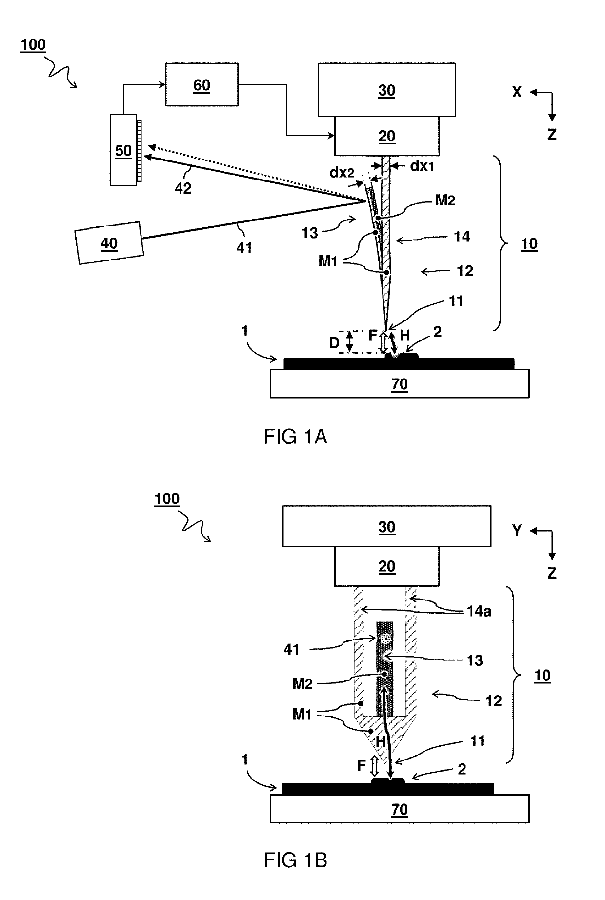
[0020]The invention is described more fully hereinafter with reference to the accompanying drawings, in which embodiments of the invention are shown. This invention may, however, be embodied in many different forms and should not be construed as limited to the embodiments set forth herein. Rather, these embodiments are provided so that this disclosure will be thorough and complete, and will fully convey the scope of the invention to those skilled in the art. In the drawings, the absolute and relative sizes of systems, components, layers, and regions may be exaggerated for clarity. Embodiments may be described with reference to schematic and / or cross-section illustrations of possibly idealized embodiments and intermediate structures of the invention. In the description and drawings, like numbers refer to like elements throughout. Relative terms as well as derivatives thereof should be construed to refer to the orientation as then described or as shown in the drawing under discussion....


PUM

PropertyMeasurementUnit
point radiusaaaaaaaaaa

Abstract

Thermal probe (10) for a scanning thermal microscope (100), use, and process of manufacturing. The thermal probe (10) comprises a single-material (M1) thermal conducting body (12) consisting of a probe frame (14) ending in a probe tip (11). A bi-material (M1,M2) cantilever strip (13) is connected to the probe frame (14) in thermal communication with the probe tip (11). The cantilever strip (13) in unbended state lies in-plane (X,Z) with the probe tip (11). The cantilever strip (13) comprises layers of material (M1,M2) having different coefficients of thermal expansion configured to bend the cantilever strip (13) with respect to the single-material thermal conducting body (12) as a function of the heat exchange (H) between the probe tip (11) and the microscopic structure (2) for measuring heat exchange (H) with a sample interface (1) by means of measuring the bending of the cantilever strip (13).

Description

[0001]This application is the U.S. National Phase of, and Applicants claim priority from, International Patent Application Number PCT / NL2016 / 050426 filed 14 Jun. 2016, which claims priority from EP 15172036.4 filed 15 Jun. 2015, each of which is incorporated herein by reference.TECHNICAL FIELD AND BACKGROUND[0002]The present disclosure relates to a thermal probe for a scanning thermal microscope, use of the thermal probe, and a process of manufacturing the thermal probe.[0003]Local temperature and thermal conductivity of a sample interface can be measured e.g. using a scanning thermal microscope (SThM) with a thermal probe comprising a probe tip. Generally, when two bodies at different temperatures are separated by a gap, they can exchange heat via thermal radiation. In the far-field approximation, i.e. when the gap is much larger than the characteristic thermal wavelength, the magnitude of heat transfer may be described by the classic Stefan Boltzmann law. However, when the thermal...

Claims


Application Information

Patent Timeline
Patent Type & Authority Patents(United States)
IPC IPC(8): G01Q60/58G01K5/64G01K5/62
CPCG01K5/62G01Q60/58G01K5/64
Inventor MARNANI, HAMED SADEGHIANBIJSTER, ROY JACOBUS FRANCISCUS
Owner NEDERLANDSE ORG VOOR TOEGEPAST NATUURWETENSCHAPPELIJK ONDERZOEK TNO
Features
  • R&D
  • Intellectual Property
  • Life Sciences
  • Materials
  • Tech Scout
  • Unparalleled Data Quality
  • Higher Quality Content
  • 60% Fewer Hallucinations
Learn More