
LED-based linear lamps and lighting arrangements

a technology of linear lamps and lamps, applied in the direction of fixed installation, lighting and heating apparatus, lighting support devices, etc., can solve the problems of glare from fluorescent tubes, non-uniform emission characteristics, and associated hot spots, and achieve the effect of reducing the appearance of hot spots

Active Publication Date: 2019-11-26
INTEMATIX
View PDF10 Cites 0 Cited by
  • Summary
  • Abstract
  • Description
  • Claims
  • Application Information

AI Technical Summary

Benefits of technology

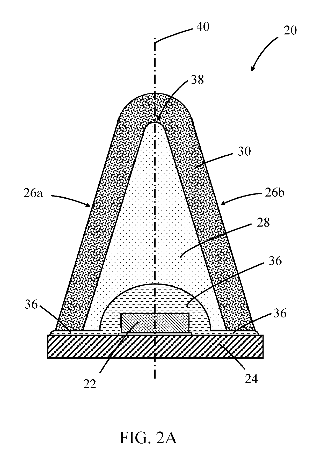
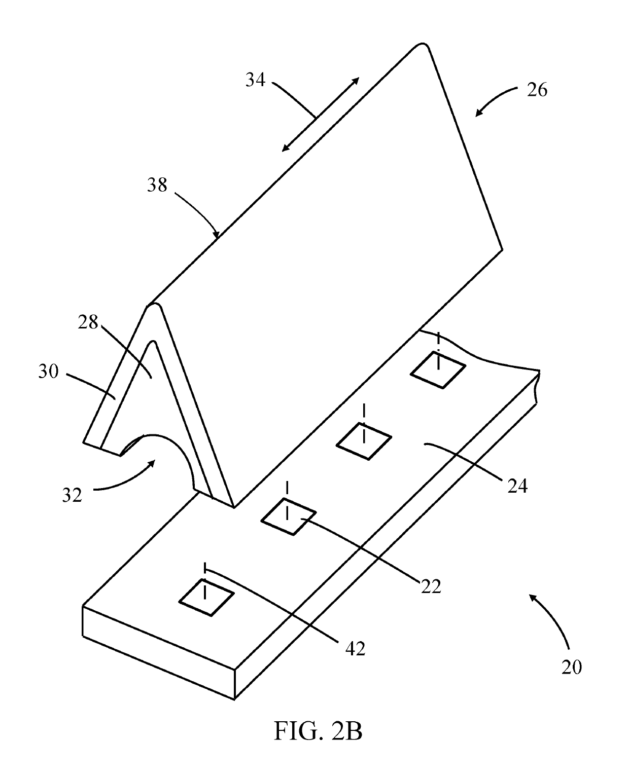
[0015]For ease of fabrication, the light transmissive core and wavelength converting portion can be integrally formed as a unitary component. In another embodiment, the component is formed as a unitary component by co-extruding the light transmissive core and wavelength converting portion. Alternatively, the component may be formed by injection molding. Some of the advantages associated with integrally forming the wavelength converting component as a unitary component include ease of manufacture, improved robustness and reliability of the component, reduced costs of manufacture, and speed of manufacture. The photoluminescence material(s), which can typically comprise an inorganic phosphor material, can be incorporated into and homogeneously distributed throughout the wavelength converting region. Alternatively and / or in addition, the photoluminescence material can be provided as a layer on a surface of the light transmissive core.
[0018]Other embodiments of the invention pertain to lighting arrangements that utilize the LED-based lamps of the invention. According to an embodiment of the invention, a lighting arrangement comprises: a housing having a light reflective interior surface and at least one LED-based lamp as described above that is located within the housing. A particular advantage of lighting arrangements utilizing lamps in accordance with embodiments of the invention is that due to the enhanced side emission characteristic of the lamps this provides a substantial improvement in emission uniformity from the entire arrangement. A further advantage is that by tailoring the side emission characteristic this enables lighting arrangements to be constructed requiring fewer LED-based linear lamps and which have a shallower profile (i.e. shallower housing) as compared with the known arrangements. For example, it is possible to construct a two foot by two foot troffer using only two LED-based linear lamps with an overall thickness of about two inches.
[0024]Other embodiments of the invention pertain to lighting arrangements that utilize the LED-based lamps of the invention. According to an embodiment of the invention a lighting arrangement comprises: a housing having a light reflective interior surface and at least one LED-based lamp utilizing a light scattering component as described above that is located within the housing. A particular advantage of lighting arrangements utilizing lamps in accordance with embodiments of the invention is that due to the enhanced side emission characteristic of the lamps this provides a substantial improvement in emission uniformity from the entire arrangement. A further advantage is that by tailoring the side emission characteristic this enables lighting arrangements to be constructed having a shallower profile (i.e. shallower housing) as compared with the known arrangements.

Problems solved by technology

To achieve desired lighting performance, most troffers are configured to receive several fluorescent tubes, since a single conventional tube by itself cannot usually generate enough light for typical applications.
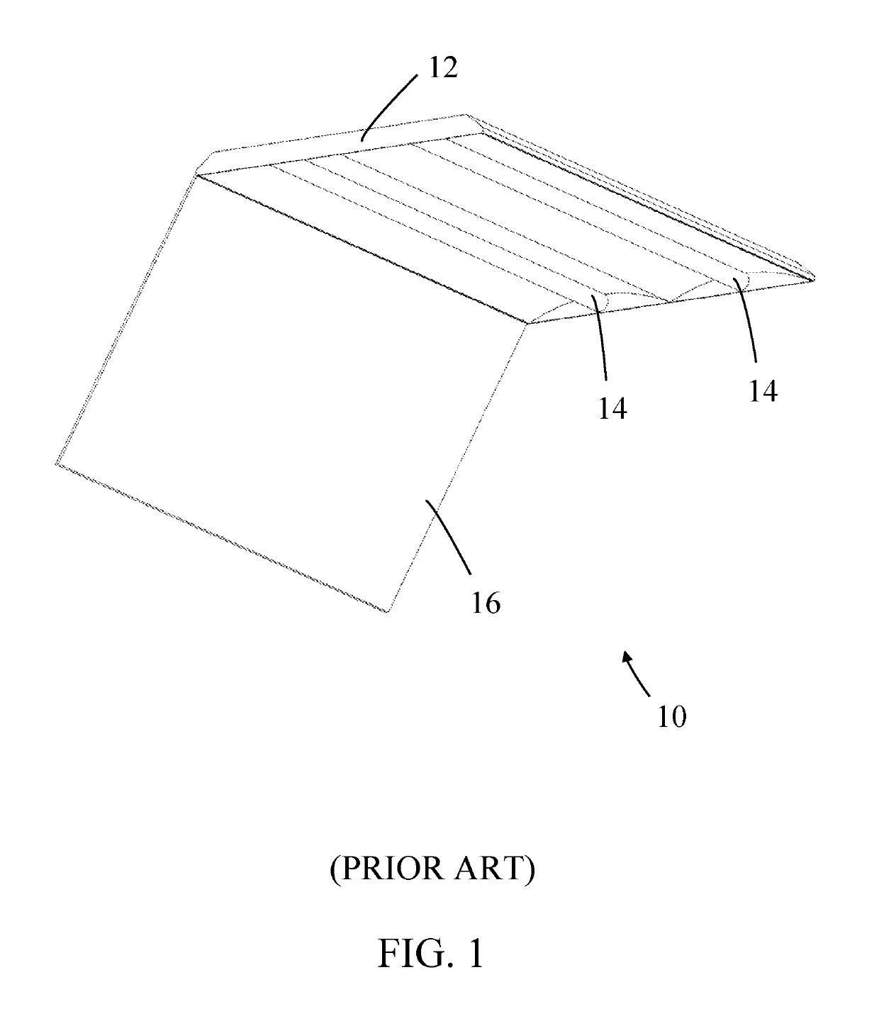
While traditional fluorescent-tube-based troffers, suspended linear, wrap-around lights and under-cabinet lighting arrangements are very common and exist in almost every commercial and office building, there are disadvantages with such lighting configurations; namely, their non-uniform emission characteristics and the appearance of glare from the fluorescent tubes.
While such LED-based linear lamps provide many benefits over traditional fluorescent lamps, such as improved efficiency and longer life expectancy, they typically possess a substantially Lambertian emission characteristic which can result in pronounced hot spots associated with each LED-based linear lamp.
Moreover, in the case of lamps comprising a linear array of discrete white LEDs, these can exhibit pronounced hot spots associated with each of the discrete white LEDs.
Such emission characteristics and hot spots are particularly undesirable in troffer applications.

Method used


Image

  • LED-based linear lamps and lighting arrangements
  • LED-based linear lamps and lighting arrangements
  • LED-based linear lamps and lighting arrangements

Examples


Embodiment Construction

[0034]Embodiments of the present invention will now be described in detail with reference to the drawings, which are provided as illustrative examples of the invention so as to enable those skilled in the art to practice the invention. Notably, the figures and examples below are not meant to limit the scope of the present invention to a single embodiment, but other embodiments are possible by way of interchange of some or all of the described or illustrated elements. Moreover, where certain elements of the present invention can be partially or fully implemented using known components, only those portions of such known components that are necessary for an understanding of the present invention will be described, and detailed descriptions of other portions of such known components will be omitted so as not to obscure the invention. In the present specification, an embodiment showing a singular component should not be considered limiting; rather, the invention is intended to encompass ...


PUM


Abstract

There is provided an elongated optical component having a direction of elongation, comprising: a light transmissive core and a wavelength converting portion disposed on an exterior surface of the light transmissive core, wherein the wavelength converting portion comprises a photoluminescence material, and wherein the wavelength converting portion has a cross-section comprising an apex.

Description

[0001]This application claims priority to, and the benefit of, U.S. Provisional Patent Application 62 / 482,516, filed Apr. 6, 2017, the contents of which are hereby incorporated by reference in their entirety for any and all purposes as if fully set forth hereinFIELD OF THE INVENTION[0002]This disclosure relates to LED-based linear lamps and lighting arrangements. In particular, although not exclusively, embodiments of the invention concern LED-based linear lamps and lighting arrangements including remote photoluminescence wavelength conversion.BACKGROUND[0003]A common lamp that has achieved great commercial success is the linear fluorescent tube lamp which is an elongated lamp with an isotropic light emission along the length of the lamp. Fluorescent tube lamps are commonly used in office, commercial, industrial and domestic applications and are available in standard sizes such as T5, T8, and T12 lamps.[0004]A lighting arrangement that is commonly used in office and commercial appli...

Claims


Application Information

Patent Timeline
Patent Type & Authority Patents(United States)
IPC IPC(8): F21V21/00F21V13/08F21V9/08F21V9/30F21K9/275F21V5/10F21V9/32F21S8/04F21V19/00F21K9/64F21Y103/10F21Y115/10
CPCF21V19/003F21K9/64F21V13/08F21S8/04F21V9/32F21V9/30F21V9/08F21V5/10F21K9/275F21Y2115/10F21Y2103/10
Inventor WEST, SCOTT
Owner INTEMATIX
Learn More