
Method and system for monitoring a motion of a subject, and corresponding computer program product

a technology for monitoring and subject motion, applied in the field of methods for monitoring a subject's motion, can solve the problems of affecting the image quality affecting the reliability of the test signal, and difficulty in keeping point artefacts or stripe artefacts caused by the test signal out of the resulting mr image, etc., to achieve complete determination or characterization, the effect of reliable and reliabl

Active Publication Date: 2021-04-29
SIEMENS HEALTHCARE GMBH
View PDF2 Cites 2 Cited by
  • Summary
  • Abstract
  • Description
  • Claims
  • Application Information

AI Technical Summary

Benefits of technology

The present invention is about improving the ability to detect and monitor motion using a monitoring signal. This is achieved by adapting the transmission and reception of the monitoring signal, which can make it more robust and resistant to noise or interference. The use of multiple emitters and coupling paths can also provide additional information and make the motion determination more reliable and complete. Overall, this technology can make motion detection more efficient and effective.

Problems solved by technology

For example, it may require a lot of additional filtering effort on a receiver side or signal processing side to separate the frequency bands of the test signal and an MR signal, and even then it may be difficult to keep point artefacts or stripe artefacts caused by the test signal out of resulting MR images.
Here, another disadvantage or problem is that a transmission power for the test signal may be limited by a dynamic range of a receiver system of a respective MRI device.
It is easily possible for the test signal to load the receiver system and in particular an analog compander in a range where additional noise or even nonlinearities in the receiver system or a receiver chain may be generated, which in turn may negatively affect image quality of resulting MR images.
Furthermore, the test signal may lead to problems with electromagnetic compatibility (EMC) and / or electromagnetic emissions exceeding safety limits.

Method used


Image

  • Method and system for monitoring a motion of a subject, and corresponding computer program product
  • Method and system for monitoring a motion of a subject, and corresponding computer program product

Examples


Embodiment Construction

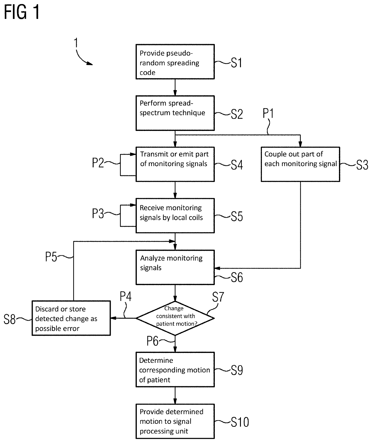
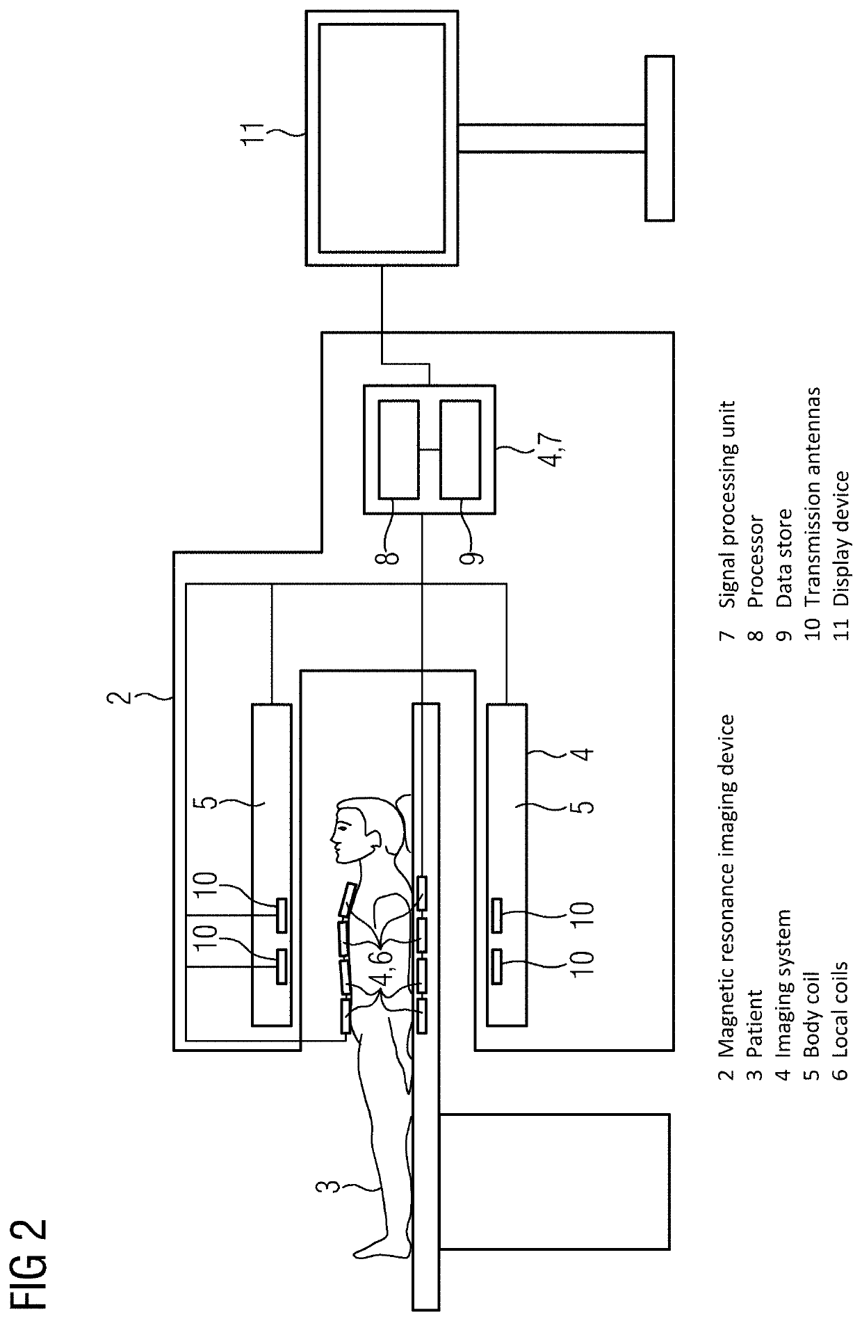
[0060]FIG. 1 schematically depicts an example for a flow chart 1 for a method for monitoring a motion of a subject. This method is illustrated here by process acts S1 to S10 and program paths P1 to P6, both of which may represent corresponding instructions, routines, or program modules of a corresponding computer program or computer program product. This computer program and therefore the corresponding method may be carried out by a system which is schematically illustrated in FIG. 2 as an MRI device 2. Below, the method, (the flow chart 1), will be explained with reference to FIG. 1 and FIG. 2.

[0061]The MRI device 2 is presently configured to image a patient 3 based on a magnetic resonance imaging technique. Here, the patient 3 serves as the subject whose motion is to be monitored using the mentioned method. In particular, the motion of the patient 3 shall be monitored while magnetic resonance imaging data (MR data) of the patient 3 is acquired by the MRI device 2. The MRI device 2...


PUM


Abstract

The disclosure relates to a method for monitoring a motion of a subject, as well as to a corresponding system and computer program product. As part of the method, a monitoring signal is emitted towards a corresponding receiver. The motion of the subject is then detected based on a change in the received monitoring signal. Therein, the monitoring signal is emitted using a spread-spectrum technique and / or using an M-to-N and multi-antenna emitter-receiver system with a set of M transmitting antennas and a set of N receiving antennas.

Description

[0001]The present patent document claims the benefit of European Patent Application No. 19205630.7, filed Oct. 28, 2019, which is hereby incorporated by reference.TECHNICAL FIELD[0002]The present disclosure relates to a method for monitoring a motion of a subject, such as a patient. The present disclosure further relates to a corresponding system and a corresponding computer program product.BACKGROUND[0003]With technological advances in medical techniques as well as in signal and data processing many applications may benefit from taking into account a motion of a respective subject, such as a patient. A known example for this is motion compensated imaging or image reconstruction, e.g., where a motion due to a heartbeat or a breathing motion of the patient may be taken into account to reduce image artefacts or blurring.[0004]For example, in magnetic resonance imaging (MRI), it has been suggested to use a pilot tone method, wherein a test signal is transmitted outside of an MR frequen...

Claims


Application Information

Patent Timeline
Patent Type & Authority Applications(United States)
IPC IPC(8): A61B5/00G01R33/58G01S11/02G01R33/34A61B5/055
CPCA61B5/721G01R33/583G01S11/02A61B5/1128A61B5/055A61B5/0035G01R33/34G01R33/56509G01R33/3692G01R33/5673A61B5/113A61B5/704
Inventor BIBER, STEPHAN
Owner SIEMENS HEALTHCARE GMBH
Learn More