Rear vehicle-body structure of vehicle

a vehicle and rear body technology, applied in the direction of vehicle components, superstructure subunits, roofs, etc., can solve the problem that the width of the support face portion is not necessarily increased

Active Publication Date: 2019-12-03
MAZDA MOTOR CORP
View PDF34 Cites 5 Cited by
  • Summary
  • Abstract
  • Description
  • Claims
  • Application Information

AI Technical Summary

Benefits of technology

[0007]Accordingly, an object of the present invention is to provide a rear vehicle-body structure of a vehicle in which a damper of a suspension which is positioned on an outward side, in the vehicle width direction, of a side frame is supported by a suspension housing, which can properly enlarge the cabin space and secure the surface rigidity of a support face portion of the suspension housing.

Problems solved by technology

Further, in the case where the distance, in the vehicle width direction, between the side frame and the damper is large, the width of the support face portion is not necessarily increased as long as the width of the level floor portion of the suspension housing is increased.

Method used


Image

  • Rear vehicle-body structure of vehicle
  • Rear vehicle-body structure of vehicle
  • Rear vehicle-body structure of vehicle

Examples


embodiment 1

[0048]A rear vehicle-body structure of a vehicle according to a first embodiment will be described referring to FIGS. 1-16.

[0049][Whole Structure]

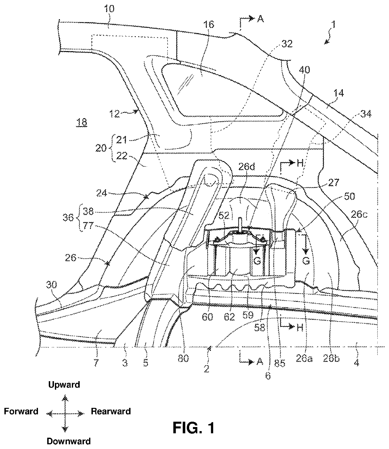
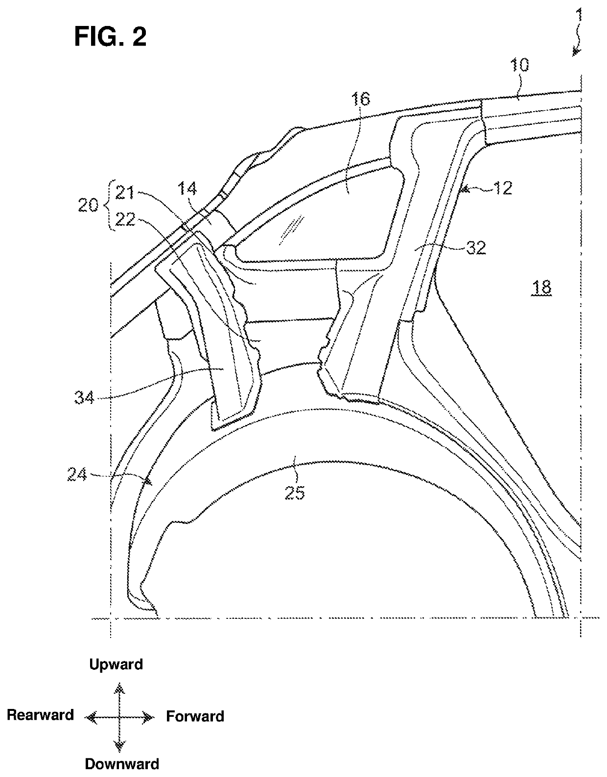
[0050]As shown in FIGS. 1 and 2, an automotive vehicle 1 which is provided with the rear vehicle-body structure of the vehicle according to an embodiment comprises a floor panel 2 which forms a floor portion of a space in a cabin, a side frame 6 which extends in a vehicle longitudinal direction along an outward-side edge portion, in a vehicle width direction, of the floor panel 2, a roof side rail 10 which extends in the vehicle longitudinal direction along an outward-side edge portion, in the vehicle width direction, of a roof panel (not illustrated), and plural pillar portions 12, 14 which extend downward from the roof side rail 10.

[0051]The side frame 6, the roof side rail 10, and the pillar portions 12, 14 are provided at each of both sides of the vehicle body, respectively, but each figure of the accompanying drawings illustrates only...

embodiment 2

[0212]A rear vehicle-body structure of a vehicle according to a second embodiment will be described referring to FIGS. 18-23. Descriptions of the same structures of the second embodiment as the first embodiment are omitted here and the same reference characters are used in FIGS. 18-23.

[0213]As shown in the perspective view of FIG. 18 and the side view of FIG. 19, a suspension housing 200 which is different from the suspension housing 50 of the first embodiment (see FIG. 1) is used in the second embodiment.

[0214]The other structures than the suspension housing 200 in the rear vehicle-body structure of the vehicle according to the second embodiment are almost similar to the first embodiment. Herein, while the load transmission portion 27 and the upper-side brace member 38 of the first embodiment are not provided in the second embodiment, these may be provided like the first embodiment.

[0215]The structure of the suspension housing 200 of the second embodiment will be described referrin...


PUM


Abstract

A rear vehicle-body structure of a vehicle comprises a wheel house, a side frame, a suspension comprising a damper, and a suspension housing connecting the side frame and the wheel house. The suspension housing includes a support face portion for supporting the damper, a level floor portion which extends outward from its connection portion to the side frame, and a vertical wall portion which extends upward from an outward-side edge portion, in a vehicle width direction, of the level floor portion up to an inward-side edge portion, in the vehicle width direction, of the support face portion.

Description

BACKGROUND OF THE INVENTION[0001]The present invention relates to a rear vehicle-body structure of a vehicle which comprises a suspension housing.[0002]As disclosed in Japanese Patent Laid-Open Publication No. 2009-137374, there is a case where at a vehicle-body rear portion is provided a suspension housing for supporting a damper of a suspension between a side frame extending in a vehicle longitudinal direction and a wheel house housing a rear wheel.[0003]The suspension housing disclosed in the above-described patent document comprises a support face portion to which an upper end portion of the damper is fixed, a vertical wall portion which extends downward from an inward-side edge portion, in a vehicle width direction, of the support face portion, and a flange portion which is provided at a lower end portion of the vertical wall portion, and this suspension housing is joined to an upper face of the side frame at the flange portion.[0004]Further, the suspension housing includes plu...

Claims


Application Information

Patent Timeline
Patent Type & Authority Patents(United States)
IPC IPC(8): B60J7/00B62D25/08B62D25/02
CPCB62D25/088B62D25/02
Inventor MASUDA, AKIYOSHIWATANABE, SHIGEAKITSUKAMOTO, HIDEYUKIMATSUOKA, HIDENORI
Owner MAZDA MOTOR CORP
Why Eureka
Try Eureka