Obstacle detection device

a detection device and obstruction technology, applied in the direction of mechanical machines/dredgers, using reradiation, instruments, etc., can solve the problems of unnecessarily occurring alarms, operation stops, and low travelling body

Active Publication Date: 2020-01-07
KOBELCO CONSTR MASCH CO LTD
View PDF26 Cites 7 Cited by
  • Summary
  • Abstract
  • Description
  • Claims
  • Application Information

AI Technical Summary

Benefits of technology

[0006]An object of the present invention is to provide an obstacle detection device which prevents a component of a construction machine from being detected as an obstacle and an operation stop of the construction machine from being excessively performed.
[0008]According to the present invention, it is possible to prevent a component of a construction machine from being detected as an obstacle and an operation stop of the construction machine from being excessively performed.

Problems solved by technology

However, in the technique of Patent Literature 1, when directivity of the millimeter wave radar provided on the upper slewing body is directed toward the ground in order to widen a detection range, a lower travelling body is detected as the obstacle, and operation stops and alarms unnecessarily occur frequently.

Method used


Image

  • Obstacle detection device
  • Obstacle detection device
  • Obstacle detection device

Examples


second modification

[0108](2) Second Modification

[0109]FIG. 12 is a view showing a monitoring region R in a second modification of the present invention. In FIG. 12, section (a) shows monitoring regions R-1 and R-2 as seen from the top, and section (b) shows the monitoring regions R-1 and R-2 when a construction machine 1 is seen from the rear toward the front. In FIG. 12, a slewing angle α of an upper slewing body 3 and a lower travelling body 2 is 90 degrees, and the upper slewing body 3 takes a lateral posture with respect to the lower travelling body 2.

[0110]Refer to section (a) of FIG. 12. In a case where an obstacle is present behind the upper slewing body 3, when the slewing angle α is 90 degrees, even if the lower travelling body 2 moves in a front-rear direction or the upper slewing body 3 slews, a possibility of the construction machine 1 colliding with the obstacle is low. In this case, there is no need to set a monitoring region R-3 behind the upper slewing body 3.

[0111]Therefore, in the se...

third modification

[0113](3) Third Modification

[0114]When an obstacle enters a monitoring region R-1 or R-2 and a monitoring region R-3, a stop control section 222 may automatically stop both slewing operation and travelling operation regardless of a slewing angle α.

Summary of Embodiment

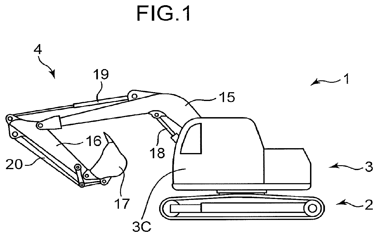
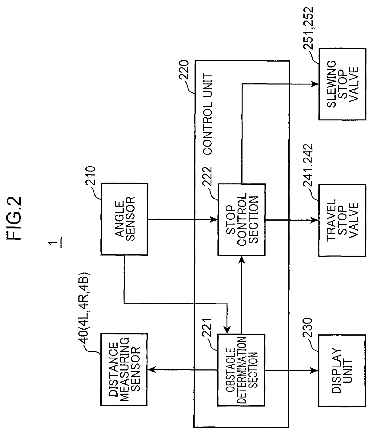
[0115]An obstacle detection device according to an aspect of the present invention is an obstacle detection device for a construction machine including a lower travelling body and an upper slewing body pivotally mounted on an upper portion of the lower travelling body, including: an object detection unit provided on the upper slewing body and for detecting a three-dimensional position of an object located around the construction machine; an angle detection unit for detecting a slewing angle of the upper slewing body with respect to the lower travelling body; and an obstacle determination section for setting a monitoring region around the construction machine so that a region indicating a component of the construction m...


PUM


Abstract

When an object detected by a distance measuring sensor is located in a monitoring region set in a blind spot of an operator, an obstacle determination section determines the detected object as an obstacle. Then, the obstacle determination section sets a monitoring region so that a region indicating a lower travelling body (2) is excluded according to a slewing angle detected by an angle sensor. Based on the slewing angle detected by the angle sensor, a stop control section determines a component, of at least one of the lower travelling body and an upper slewing body, which has a possibility that a construction machine collides with the obstacle when the component is operated, and stops operation of the determined component.

Description

TECHNICAL FIELD[0001]The present invention relates to an obstacle detection device for a construction machine provided with a lower travelling body and an upper slewing body which is pivotally mounted on an upper portion of the lower travelling body and includes a cabin that an operator boards.BACKGROUND ART[0002]In recent years, in a construction machine having an upper slewing body such as a hydraulic excavator or a crane, by detecting an obstacle located in surroundings and stopping an operation or issuing an alarm according to a detection result, interference between the upper slewing body and the obstacle is prevented in advance.[0003]Patent Literature 1 discloses a technique in which, when it is detected that an obstacle detected by a millimeter wave radar is located in a collision preventing region provided around a work machine and operation in a direction to approach the obstacle is performed, operation of an upper slewing body is forcibly stopped.[0004]However, in the tech...

Claims


Application Information

Patent Timeline
Patent Type & Authority Patents(United States)
IPC IPC(8): G01S17/93E02F9/24E02F9/20B66C23/88G01S17/931
CPCB66C23/88E02F9/2033E02F9/24G01S17/931E02F3/43E02F9/20E02F9/26E02F9/262G01B21/047G01B21/18G01B21/22G08B21/02
Inventor KINOSHITA, AKIRAKAMIMURA, YUSUKE
Owner KOBELCO CONSTR MASCH CO LTD
Why Eureka
Try Eureka