Signal processing apparatus and signal processing method
a signal processing and signal processing technology, applied in the field of signal processing apparatus, can solve problems such as inability to evaluate properties, and achieve the effect of estimating a value sufficiently accurately and relatively easily
- Summary
- Abstract
- Description
- Claims
- Application Information
AI Technical Summary
Benefits of technology
Problems solved by technology
Method used
Image
Examples
first and second embodiments
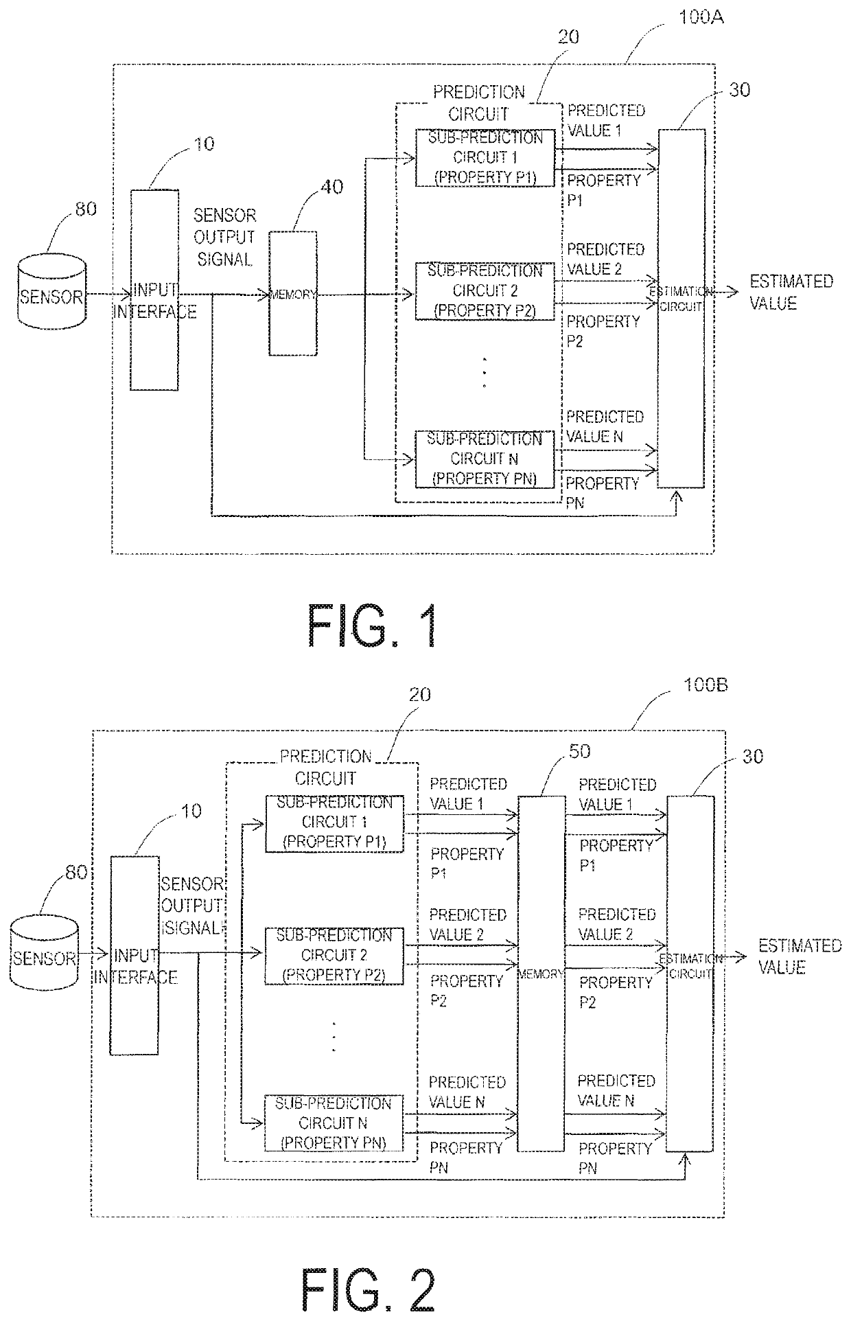
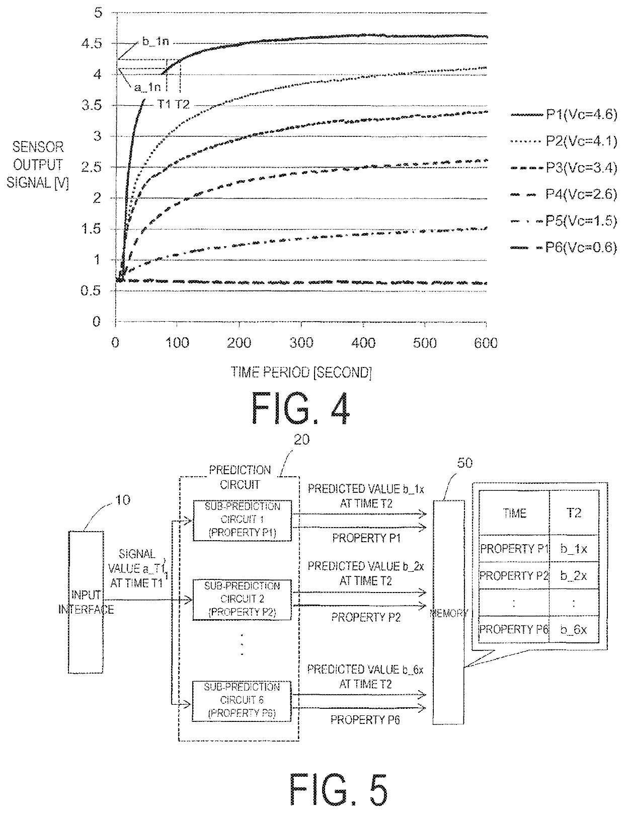
FIG. 1 schematically illustrates a configuration of a signal processing apparatus 100A according to a first embodiment of the present invention. The signal processing apparatus 100A includes an input interface 10 configured to receive an output signal Va(T) from a sensor 80, a prediction circuit 20 configured to generate, on the basis of a relationship, different depending on each of a plurality of converged values Vc corresponding to the respectively different parameter values, a plurality of predicted values Vb_T2 corresponding to a value of the output signal that would be obtained at a time T2 after a time T1, in a transition response period before a response time period Tr elapses where Tr denotes a response time period required for a value of the output signal Va(T) to become a converged value Vc corresponding to a value P of a parameter representing a certain property of an object to be measured, in accordance with the value of the output signal Va_T1 obtained at the time T1, ...
third embodiment
Instead of the sub-prediction circuit provided in the signal processing apparatus 100A according to the first embodiment and the prediction circuit 20 provided in the 100B according to the second embodiment, a neural network configured so that the output signal, when the object to be measured is a certain property, is input to generate the predicted value may be used.
An example of a configuration of the neural network is illustrated in FIG. 9. The neural network illustrated in FIG. 9 is a neural network including one node of an input layer, five nodes of an intermediate layer, and one node of an output layer. For example, when the sub-prediction circuit 1 corresponding to the property P1 is input with the output signal a_T at the time T, the learning of the neural network is performed so that b_1x is generated as the predicted value at the time T+Tc. For the learning of the neural network, a generally-known scheme such as back propagation may be used.
When a neural network is concern...
fourth embodiment
The estimation circuit 30 provided in the signal processing apparatus according to the above-described first to third embodiments generate, as described with reference to FIG. 5 and FIG. 6, the estimated value on a direct basis of the error between the output signal and the predicted value. When generating the estimated value on the basis of the error between the output signal and the predicted value, the error may be directly utilized. In addition, as in the estimation circuit 30 illustrated in a fourth embodiment, the estimated value may also be generated on the basis of the accumulated value of the errors.
As illustrated in FIG. 10, the estimation circuit 30 provided in the signal processing apparatus according to the fourth embodiment is configured so that the estimated value of a property of the object to be measured is generated, in accordance with the output signal, on the basis of the accumulated value of the errors of the predicted value. Specifically, the estimation circuit...
PUM
| Property | Measurement | Unit |
|---|---|---|
| time | aaaaa | aaaaa |
| time | aaaaa | aaaaa |
| time | aaaaa | aaaaa |
Abstract
Description
Claims
Application Information
 - R&D
- Intellectual Property
- Life Sciences
- Materials
- Tech Scout
- Unparalleled Data Quality
- Higher Quality Content
- 60% Fewer Hallucinations
Browse by: Latest US Patents, China's latest patents, Technical Efficacy Thesaurus, Application Domain, Technology Topic, Popular Technical Reports.
© 2025 PatSnap. All rights reserved.Legal|Privacy policy|Modern Slavery Act Transparency Statement|Sitemap|About US| Contact US: help@patsnap.com


