

Systems and methods for switched electrode stimulation for low power bioelectronics
a bioelectronic and switched electrode technology, applied in the field of tissue stimulation, can solve the problems of low voltage, low power requirements, unpredictable changes in stimulation amplitude, etc., and achieve the effect of low voltage, charge and power requirements
- Summary
- Abstract
- Description
- Claims
- Application Information
AI Technical Summary
Benefits of technology
Problems solved by technology
Method used
Image

Examples
Embodiment Construction
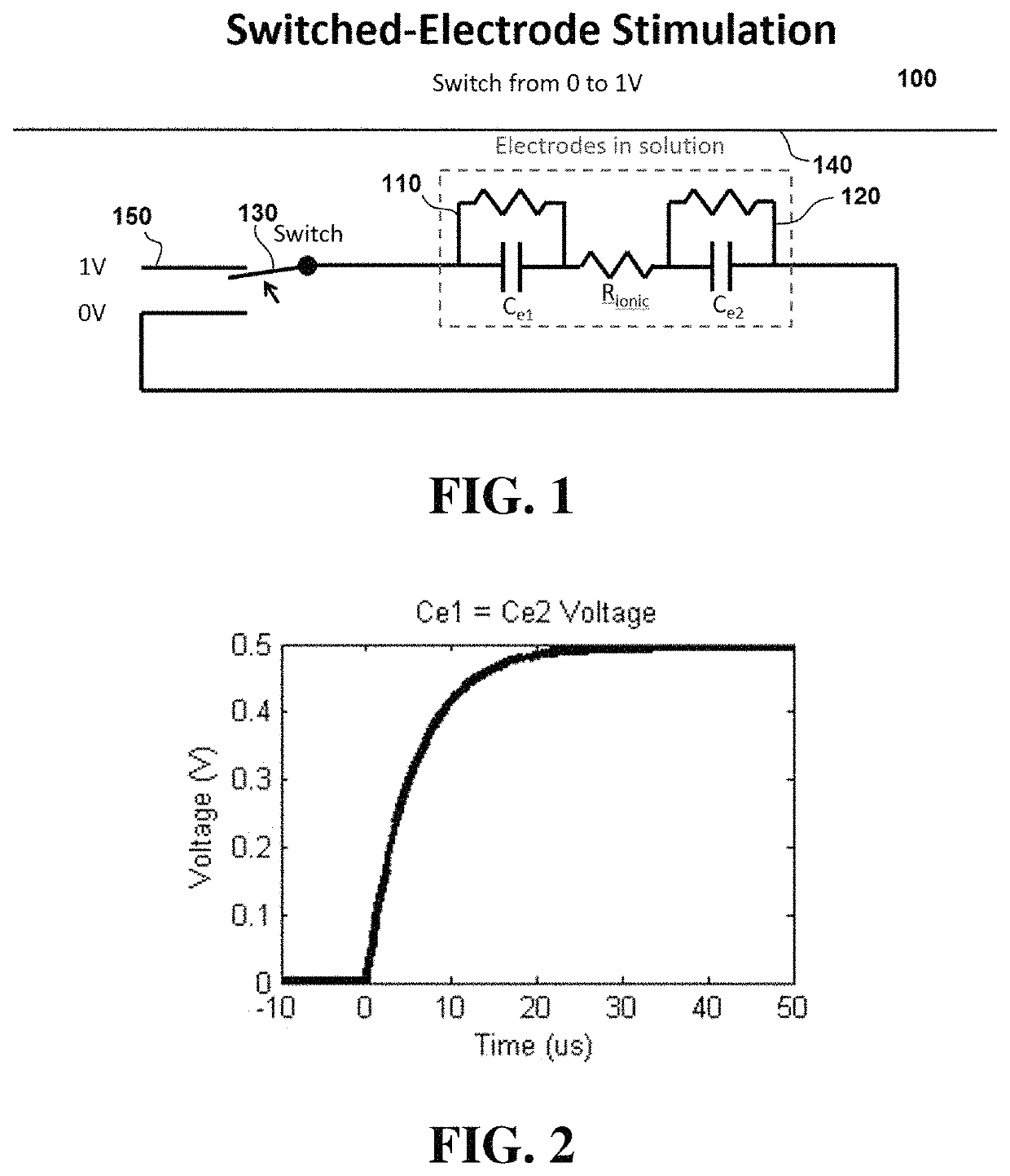
[0037]Referring now to FIG. 1, a nerve stimulation system 100 comprises first electrode 110 and second electrode 120. During operation, electrodes 110 and 120 begin at the same potential (zero volts in the embodiment shown), and one electrode is then switched via a switch 130 to a different potential (e.g., 1V) from a fixed voltage source 150. As used herein, the term “fixed voltage source” includes a voltage source that provides a relatively constant voltage level.
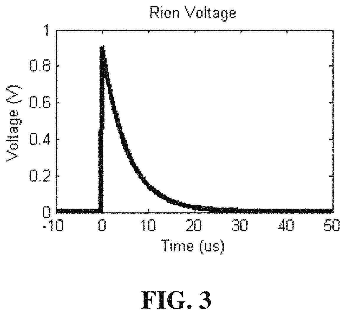
[0038]After the voltage switch is made to one electrode, current begins to flow from the electrode through tissue 140 proximal to electrodes 110 and 120. The current decreases exponentially with time due to the charging of the electrode double layer capacitance between the charged electrode and tissue 140. Once the electrode double layer capacitance has been charged, electrodes 110 and 120 are switched back to the same potential. Current is then discharged out of electrodes 110 and 120, decreasing exponentially over time....
PUM
 Abstract
Description
Claims
Application Information