Energy saving cable assembly

a technology of energy saving cable and assembly, which is applied in the integration of power network operation systems, emergency power supply arrangements, transportation and packaging, etc. it can solve the problems of unavoidable waste of energy in this low power consumption state, chargers that cannot then power up by themselves, and chargers that cannot meet the needs of charging, etc., to achieve more control over the charging function and extend the useful life of batteries

Inactive Publication Date: 2013-04-18
HORIZON TECHNOLOGIES
View PDF7 Cites 46 Cited by
  • Summary
  • Abstract
  • Description
  • Claims
  • Application Information

AI Technical Summary

Benefits of technology

[0012]In yet still another exemplary, non-limiting implementation of the present concept, a software application is provided to be installed on a portable device to control the turn-on and turn-off of the charger. The software application could be provided with the charger for use on compatible devices such as smart cell phones and portable computers. The software application may allow the user more control over the charging function. The user may select a less than full charge level (i.e. 85%) at which the charger is shut off to protect the battery of the target device from the stress of a full charge thus extending the useful life of the battery. The software may allow the user to set a convenient time each day for the charger to begin the charging cycle or to finish the charging cycle for the portable device. The software may allow the charging rate to be reduced for a longer charge cycle which also reduces stress on the battery for a longer battery life. The software can monitor the decline in battery capacity over time to warn of a weakening battery. In some forms of the present concept the software communicates with the power device through a USB cable connection. In some forms the communication is accomplished with a wireless connection to the power device. This connection may be in the form of a Bluetooth wireless connection. In another form the portable device may control the on and off state of the power device by sending a wireless signal to the smart grid to enable and disable power to the corresponding outlet.

Problems solved by technology

An AC charger of the type just described always consumes power when connected to the AC power source, regardless of whether a target device, typically a portable device, is being charged or even connected thereto.
If a charger switches to a low power state, some energy continues to be unavoidably wasted in this low power consumption state.
If a no-idle-power charger shuts off completely to save power, the charger cannot then power up by itself since it needs an external source of power to turn back on.

Method used


Image

  • Energy saving cable assembly
  • Energy saving cable assembly
  • Energy saving cable assembly

Examples


Embodiment Construction

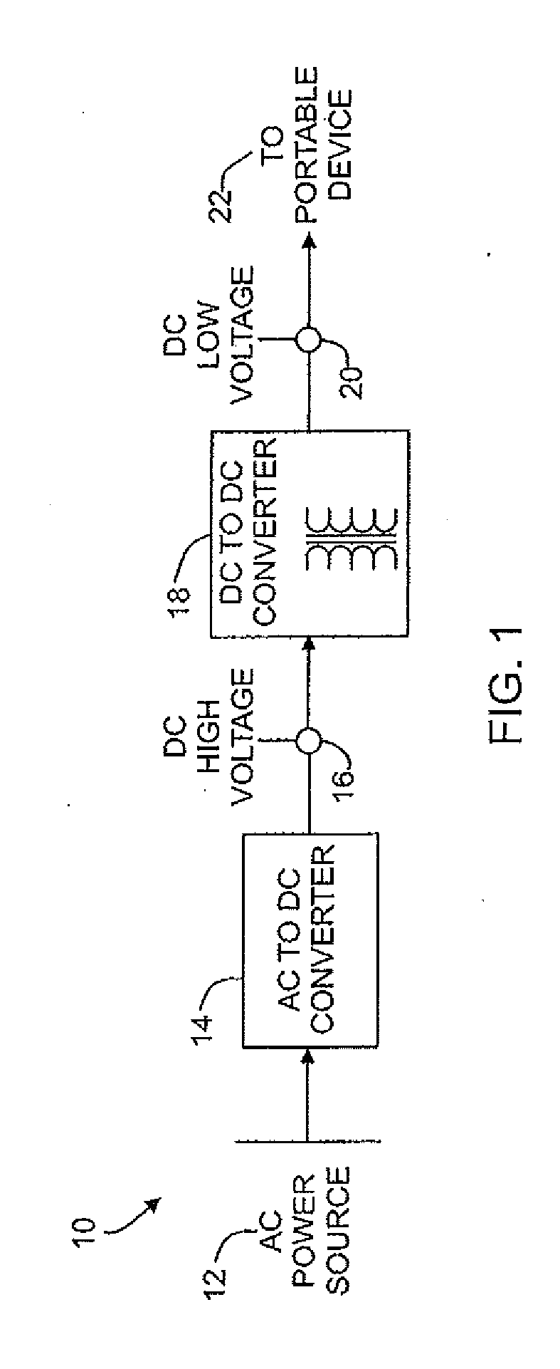
[0024]FIG. 1 illustrates a conventional AC charger 10 in which power from an external AC power source 12 flows through an AC to DC converter 14 to convert the AC input voltage to a DC output voltage. The DC output voltage may be referred to as a “high” voltage 16 which is connected as the input to a DC to DC converter 18, which changes the high DC voltage to a different level, e.g., a low voltage 20 appropriate for use by a suitable portable device 22. Thus in the illustrated example, the DC to DC converter 18 may be thought of as a step-down voltage converter. Depending upon the requirements of the portable device 22, the DC to DC converter may also contain a transformer to provide required safety isolation between the DC output of the converter 18 and the AC input to the converter 14. This AC charger 10 would always consume power when connected to the AC power source, regardless of whether a target device is being charged,or even connected thereto.

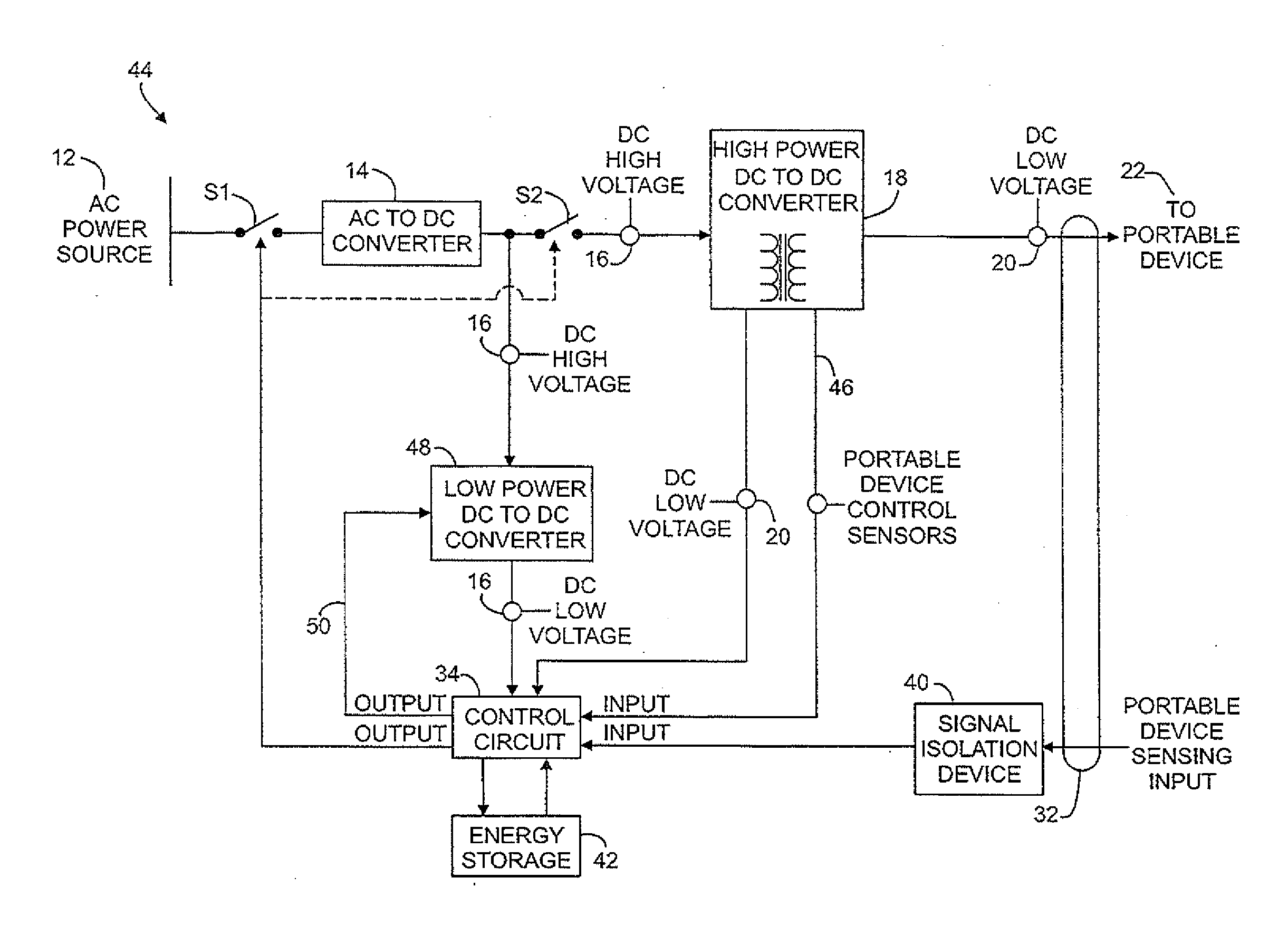
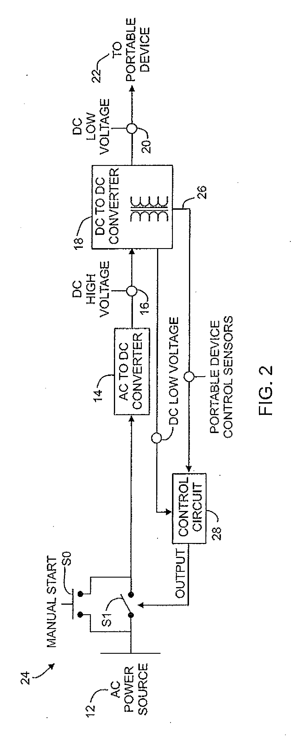
[0025]An energy saving battery po...


PUM


Abstract

A power charger circuit converts input energy to DC output energy, with the input energy flowing in a first direction such as via a cable having multiple conductors to provide the output energy, with the power charger including at least one switch having an open state and a closed state, the open state to interrupt the flow of input energy and the power charging circuit allowing for energy flow in a second direction opposite the first direction so that the switch may be moved to the closed state.

Description

CROSS-REFERENCE TO RELATED APPLICATIONS[0001]This application is a conversion of U.S. Provisional Patent Application No. 61 / 443,611 filed Feb. 16, 2011, and a conversion of U.S. Provisional Patent Application. No. 61 / 507,306 filed Jul. 13, 2011, from both of which applications priority is claimed. This application is also a continuation-in-part of U.S. patent application Ser. No. 12 / 176,261 filed Jul. 18, 2008, (now U.S. Pat. No, 7,960,648) which is a continuation-in-part of U.S. patent application Ser. No. 12 / 127,592, filed on May 27, 2008, now U.S. Pat. No. 7,910,833) and U.S. patent application Ser. No. 13 / 054,643, which is the U.S. National Stage Entry of International Application PCT / US09 / 46223 filed on Jun. 4, 2009, which was a continuation-in-part of the aforementioned U.S. patent applications Ser. Nos. 12 / 176,261, 12 / 251,898, and 12 / 251,882. The entireties of all of the foregoing are hereby incorporated by reference.BACKGROUND[0002]This application relates to power devices a...

Claims


Application Information

Patent Timeline
Patent Type & Authority Applications(United States)
IPC IPC(8): H02J7/00H02J7/02
CPCH02J7/0068H02J7/02H02J9/005H02J7/0042H02J7/0093Y04S20/20Y02B70/30H02J5/00H02J7/00711
Inventor MCGINLEY, JAMESRIMDZIUS, DONALD
Owner HORIZON TECHNOLOGIES
Why Eureka
Try Eureka