Device for securing a blanket module to a fusion reactor vacuum vessel

a blanket module and vacuum vessel technology, applied in nuclear energy generation, nuclear reactors, climate sustainability, etc., can solve the problems of reducingreducing the reducing the torque value of the threaded connection between the flexible support and the blanket module. , to achieve the effect of increasing the load-support capacity of the device, preventing possible weakening of the threaded joint, and increasing the diameter of the fastening thread

Active Publication Date: 2020-03-17
ROSSIJSKAJA FEDERATSIJA OT IMENI KOTOROJ VYSTUPAET GOSUDARSTVENNAJA KORPORATSIJA PO ATOMNOJ EHNERGII ROSATOM
View PDF7 Cites 1 Cited by
  • Summary
  • Abstract
  • Description
  • Claims
  • Application Information

AI Technical Summary

Benefits of technology

[0013]An object of the present invention is to provide a device for securing a blanket module to a fusion reactor vacuum vessel which ensures service reliability in the process of cycle operation of the fusion reactor, as well as streamlining the process of installation of the blanket module on the vacuum vessel.
[0014]The technical effect of the present invention is an increase in permitted torque value of the threaded joint between the flexible support and the module, which increases a load-support capacity of the device, prevents possible weakening of the threaded joint by virtue of self-locking ability, and provides for self-compensation of angular and axial displacements occurring as the module is mounted on the vacuum vessel.
[0021]Making the threaded fastener as a locknut and the rigid connection of the displacement compensator with the module prevents possible weakening of the threaded joint during operation of the fusion reactor by virtue of self-locking ability. Replacing the bolt with the locknut enables to increase the load-support capacity of the device by virtue of increasing the diameter of the fastening thread, which allows to increase tension of the threaded connection between the flexible support and the blanket module and, therefore, to increase the permitted loads received from the blanket module with a guaranteed non-gapping of the joints. Furthermore, by means of eliminating the bolt component (replacing the bolt with the locknut) a space for the spacer sleeve became available, and the spacer sleeve provides for a pivot joint of the flexible support with the displacement compensator, provides for a flexible joint with a locking screw and a flexible joint of the coupling sleeve with relation to a locknut. The above configuration enables self-compensation of angular and axial displacements occurring as the module is mounted on the vacuum vessel.
[0022]The essential features described above as compared to the closest analog result in the reliable operation of the device for securing the module to the vacuum vessel in the severe conditions in the fusion reactor and facilitate installation works during mounting process.

Problems solved by technology

The known device for securing the blanket module to the vacuum vessel of the fusion reactor has a disadvantage that additional machining of the flexible support is required along its length to compensate angular and shear displacements arising from manufacturing errors of the vacuum vessel during assembling process of the module.
The known device for securing the blanket module to the vacuum vessel of the fusion reactor as described above has a disadvantage that the threaded connection between the bolt and the blanket module is weakened in the process of cycle operation of the fusion reactor.
In addition, another disadvantage of the known device can be defined as the limitation of the permitted torque value for the threaded connection of the flexible support and blanket module due to small cross-section area of the rod portion of the bolt caused by the inner mounting hole.

Method used


Image

  • Device for securing a blanket module to a fusion reactor vacuum vessel

Examples


Embodiment Construction

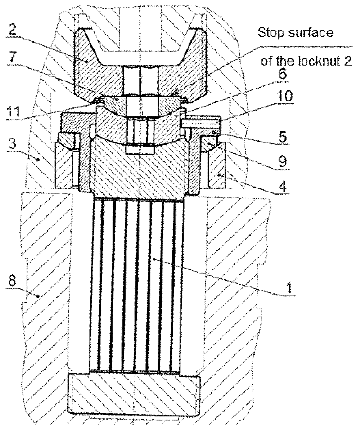
[0025]The device for securing the blanket module to the vacuum vessel of the fusion reactor has a flexible support 1 with flanges, a fastening member 2 and a displacement compensator positioned at the flange of the flexible support facing the blanket module 3, the displacement compensator comprising a supporting sleeve 4, a locking screw 5, a spacer sleeve 6 and a coupling sleeve 7 with a spherical protuberance. Flexible support 1 is made in the form of rods positioned between the two flanges. The flanges of the flexible support 1 are configured to have a male thread, and one of the flanges threadably couples the flexible support 1 to the vacuum vessel 8, and the other flange having a concave spherical end face couples the flexible support 1 to the blanket module 3 through the displacement compensator by means of the threaded fastening member 2 connected with a mounting socket of the blanket module 3. The threaded fastening member 2 is configured as a locknut with a male thread. The...


PUM


Abstract

The invention relates to the field of thermonuclear fusion and can be used for securing a blanket module to a vacuum vessel of a fusion reactor. The connecting device comprises a flexible support in the form of rods mounted between an upper flange having a concave spherical surface and a lower flange; a displacement compensator mounted on the upper flange; and a male-threaded locknut. The displacement compensator is fixedly connected to the blanket module and comprises a locking screw and a supporting sleeve, which are pivotally interconnected, a spacer sleeve, and a coupling sleeve with a spherical protuberance. The spacer sleeve is movably connected to the locking screw and pivotally connected to the upper flange of the flexible support and to the spherical protuberance of the coupling sleeve. The coupling sleeve is fixedly connected to a stop surface of the locknut.

Description

CROSS-REFERENCE TO RELATED APPLICATIONS[0001]This application is a National Stage of PCT / RU2017 / 000154, filed Mar. 20, 2017 that claims the priority of Russian Patent Application No. 2016110190, filed on Mar. 21, 2016, which are incorporated herein by reference in their entirety for all purposes.TECHNICAL FIELD[0002]The invention relates to the field of thermonuclear fusion and can be used in devices for securing a blanket module to the vacuum vessel of a fusion reactor.BACKGROUND ART[0003]There is known a device for securing a blanket module to a vacuum vessel of a fusion reactor comprising flexible hollow support designed in the form of rods mounted between two flanges, wherein one of the flanges couples the support with the vacuum vessel and the other flange is connected with the blanket module by means of a threaded fastener with a locking sleeve fixed in the blanket module by deformation (Russian Patent No. 2563975, IPC G21Bl / 17, published on Sep. 27, 2015).[0004]The known devi...

Claims


Application Information

Patent Timeline
Patent Type & Authority Patents(United States)
IPC IPC(8): G21B1/13G21B1/17
CPCG21B1/13G21B1/17Y02E30/128Y02E30/10
Inventor KOLGANOV, VLADIMIR UR'EVICHKHOMYAKOV, SERGEY EMIL'EVICHPODDUBNYJ, IVAN IGOREVICH
Owner ROSSIJSKAJA FEDERATSIJA OT IMENI KOTOROJ VYSTUPAET GOSUDARSTVENNAJA KORPORATSIJA PO ATOMNOJ EHNERGII ROSATOM
Why Eureka
Try Eureka