Apparatus comprising a phase-locked loop

a phase-locked loop and apparatus technology, applied in the direction of electrical apparatus, pulse automatic control, etc., can solve the problems of not offering integrated adcs, affecting and reducing the angular resolution of sensors

Active Publication Date: 2020-03-17
NXP BV
View PDF19 Cites 0 Cited by
  • Summary
  • Abstract
  • Description
  • Claims
  • Application Information

AI Technical Summary

Benefits of technology

[0016]By enabling the output clock signal to be delayed or advanced relative to the feedback clock signal, the present invention enables compensation of timing differences due to delays in transmission of a reference clock signal between different elements of the apparatus, thereby improving clock synchronisation. In particular, the present invention enables compensation of timing delays due to PCB skew.
[0026]This may help to ensure equal delays at the master and slave dividers.
[0028]This may enable outputs of opposite phase to be available without incurring a relative delay.

Problems solved by technology

Otherwise, errors in the angular position estimates are introduced during signal processing in the base-band, and the advantages of using a large array to increase sensor angular resolution may be lost.
However these circuits do not offer integrated ADCs and as such do not deal with the requirement for ADC clock synchronization discussed above.

Method used


Image

  • Apparatus comprising a phase-locked loop
  • Apparatus comprising a phase-locked loop
  • Apparatus comprising a phase-locked loop

Examples


Embodiment Construction

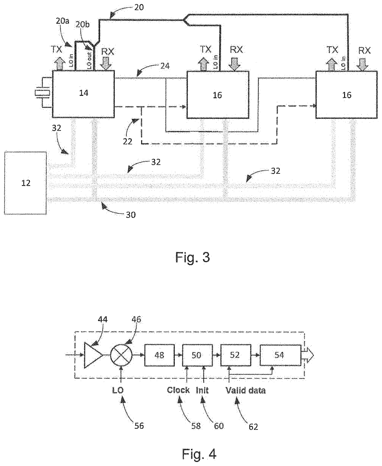
[0070]FIG. 3 shows a configuration of a multiple-chip radar sensor system 10 according to an embodiment of the present invention. The system 10 comprises a main computing unit (MCU) 12, a “master” integrated chip (IC) 14 and a number of “slave” ICs 16 (of which two are shown in FIG. 3).

[0071]The “master” IC 14 provides a number of signals to the “slave” ICs 16, including: a local oscillator signal (LO) 20, used for the transmit (TX) amplifiers and receiver (RX) mixers (not shown in FIG. 3); a “chirp start” signal 22, used to trigger the starting point of the timing engines (not shown in FIG. 3) within each IC 14, 16; and a 40 MHz reference clock signal 24, used as a time base for synchronization of the sampling moments on the ADCs on the master and slave ICs. In the arrangement shown in FIG. 3, the master IC 14 has a local oscillator (LO) input port (“LO in”, 20a) in addition to the local oscillator output port (“LO out”, 20b). The use of separate LO input and output ports 20a, 20b ...


PUM


Abstract

There is disclosed an apparatus comprising a first phase-locked loop comprising: a phase detector (302, 304), arranged to receive a reference clock signal (306) and a feedback clock signal (308) and to output a frequency control signal based on a phase difference between the reference clock signal (306) and the feedback clock signal (308); a variable-frequency oscillator (312, 314) arranged to output an oscillator signal having a frequency dependent on said frequency control signal; first divider circuitry (316) for generating said feedback clock signal (308) by frequency-dividing said oscillator signal; and second divider circuitry (320) for generating an output clock signal (3220 by frequency-dividing said oscillator signal; wherein a phase relation between said first divider circuitry (316) and said second divider circuitry (320) is adjustable to delay or advance said output clock signal (322) relative to said feedback clock signal (308). The apparatus may be a radar receiver or transceiver.

Description

CROSS-REFERENCE TO RELATED APPLICATIONS[0001]This application claims the priority under 35 U.S.C. § 119 of European Patent application no. 17199331.4, filed on 31 Oct. 2017, the contents of which are incorporated by reference herein.FIELD OF THE INVENTION[0002]The present invention relates to an apparatus comprising a phase-locked loop. In particular, but not exclusively, it relates to a radar receiver or transceiver.BACKGROUND OF THE INVENTION[0003]High performance automotive radar sensors for autonomous driving need to comply with stringent angular resolution requirements. Angular resolution relates directly to the system total antenna aperture, which in turn normally relates to the number of receive antennas and their localization with respect to each other.[0004]To avoid so-called grating lobes in the angular response (i.e. false target detection at certain angular positions), it is necessary that the antennas be located not further than λ / 2 from each other, with λ being the wav...

Claims


Application Information

Patent Timeline
Patent Type & Authority Patents(United States)
IPC IPC(8): H03L7/06H03L7/099H03L7/18H03L7/091H03L7/185H03L7/191
CPCH03L7/18H03L7/185H03L7/191H03L7/091H03L7/0992
Inventor VAUCHER, CICERO SILVEIRADERKSEN, SANDERJANSSEN, ERWINKUP, BERNARDUS JOHANNES MARTINUS
Owner NXP BV
Why Eureka
Try Eureka