Illuminator and projector

a technology of projectors and illuminators, applied in the field of illuminator and projectors, can solve the problems of color unevenness in images and the inability to adjust the size of illuminator,

Active Publication Date: 2020-03-31
SEIKO EPSON CORP
View PDF7 Cites 3 Cited by
  • Summary
  • Abstract
  • Description
  • Claims
  • Application Information

AI Technical Summary

Benefits of technology

[0005]An advantage of some aspects of the invention is to provide a compact illuminator that outputs light having a small degree of color unevenness. Another advantage of some aspects of the invention is to provide a projector that excels in image quality.
[0009]According to the configuration described above, since the number of first light emitters, which each have high light emission efficiency, is small, and the numbers of second light emitters and third light emitters, which each have low light emission efficiency are large, a satisfactory color balance of the light from the light source apparatus is readily achieved. That is, the white balance of the light that exits out of the light source apparatus can be readily adjusted.
[0011]According to the configuration described above, a compact illuminator capable of outputting white light can be achieved.
[0013]According to the configuration described above, the size of the light source apparatus can be reduced. Further, the central axis of the second light having the second color and formed by the plurality of second light emitters coincides with the central axis of the first light having the first color. Similarly, the central axis of the third light having the third color and formed by the plurality of third light emitters coincides with the central axis of the first light. In the present specification, the central axis of the spread (distribution) of light is referred to as the central axis of the light.
[0023]According to the configuration described above, the number of parts of the illuminator and the size thereof can be reduced.
[0025]The projector according to the aspect of the invention, which includes the illuminator according to the aspect of the invention, can project an image having a small amount of color unevenness.

Problems solved by technology

As a result, the intensity of the blue light cannot be sufficiently homogenized as compared with the intensity of each of the green light and the red light, resulting in a problem of color unevenness in an image.
In this case, however, the size of the illuminator undesirably increases.

Method used


Image

  • Illuminator and projector
  • Illuminator and projector
  • Illuminator and projector

Examples


first embodiment

[0036]A first embodiment of the invention will be described below with reference to FIGS. 1 to 5.

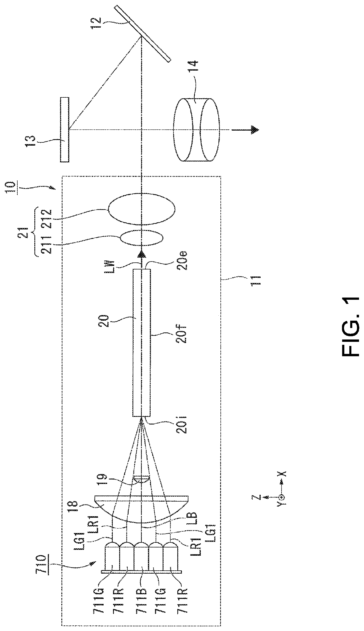
[0037]FIG. 1 is a schematic configuration diagram of a projector according to the first embodiment.

[0038]In the following drawings, each component is drawn at a different dimensional scale depending on the component in some cases for clarity of the component. In the drawings, the direction in which an illuminator outputs light is an X-axis direction, and the directions perpendicular to each other in a plane perpendicular to the X-axis direction are a Y-axis direction and a Z-axis direction.

[0039]A projector 10 according to the present embodiment includes an illuminator 11, a light guide system 12, a micromirror-type light modulator 13, and a projection optical apparatus 14, as shown in FIG. 1. The illuminator 11 includes a light source apparatus 710, a light focusing lens 18 (first lens), a blue light adjustment lens 19 (second lens), a rod integrator 20, and a pickup system 21.

[0040]FIG...

second embodiment

[0092]A second embodiment of the invention will be described below with reference to FIG. 7.

[0093]The configuration of a projector according to the second embodiment is roughly the same as that in the first embodiment but differs therefrom in terms of the configuration of the illuminator. The overall projector will therefore not be described, and only different portions will be described.

[0094]FIG. 7 is a schematic configuration diagram of an illuminator according to the second embodiment.

[0095]In FIG. 7, components common to those in the drawings used in the first embodiment have the same reference characters and will not be described.

[0096]In an illuminator 31 according to the present embodiment, a blue light adjustment lens 32 is formed of a spherical concave lens having a flat surface and a concave surface, as shown in FIG. 7. The blue light adjustment lens 32 is so sized that the red light LR emitted from the red semiconductor lasers 711R or the green light LG emitted from the ...

third embodiment

[0100]A third embodiment of the invention will be described below with reference to FIGS. 8 and 9.

[0101]The configuration of a projector according to the third embodiment is roughly the same as that in the first embodiment but differs therefrom in terms of the configuration of the illuminator. The overall projector will therefore not be described, and only different portions will be described.

[0102]FIG. 8 shows an illuminator according to the third embodiment viewed along the Z-axis direction. FIG. 9 shows the illuminator according to the third embodiment viewed along the Y-axis direction.

[0103]In FIGS. 8 and 9, components common to those in the drawings used in the first embodiment have the same reference characters and will not be described.

[0104]In an illuminator 41 according to the present embodiment, a blue light adjustment lens 42 is formed of an anamorphic convex lens formed of convex surfaces having different values of curvature in two directions perpendicular to each other ...


PUM


Abstract

An illuminator according to an aspect of the invention includes a light source apparatus including a first light emitter that emits first light having a first color, a plurality of second light emitters that each emit second light having a second color, and a plurality of third light emitters that each emit third light having a third color, a rod integrator that combines the first light, the second light, and the third light with one another, a first lens that causes the first light, the second light, and the third light to be focused in the rod integrator, and a second lens that transmits only the first light out of the first light, the second light, and the third light. The plurality of second light emitters and the plurality of third light emitters are so disposed as to surround the first light emitter.

Description

BACKGROUND1. Technical Field[0001]The present invention relates to an illuminator and a projector.2. Related Art[0002]In recent years, to enhance the performance of a projector, attention has been directed to a projector using a laser light source, which is a light source having a wide color gamut and is highly efficient. JP-T-2009-520233 discloses a projector including a rod integrator for mixing red light, green light, and blue light emitted from laser light sources with one another and homogenizing the intensity of the mixed light.[0003]Since the light emission efficiency of a laser light source varies on an emitted light color basis, the number of laser light sources necessary for white balance appropriate for image display varies on an emitted light color basis. In general, the light emission efficiency of a blue laser light source is higher than the light emission efficiency of each of a green laser light source and a red laser light source. The number of laser light sources n...

Claims


Application Information

Patent Timeline
Patent Type & Authority Patents(United States)
IPC IPC(8): G03B21/20G03B21/00
CPCG03B21/2013G03B21/208G03B21/2033G03B21/008
Inventor AKIYAMA, KOICHI
Owner SEIKO EPSON CORP
Why Eureka
Try Eureka