Fastening device

a technology of fastening device and lace, which is applied in the direction of mechanical control device, fastening, instruments, etc., can solve the problems of easy loosening of knots, easy release of lace, and many inconveniences, and achieve the effect of simplifying the structure purpos

Active Publication Date: 2020-05-26
CHEN CHIN CHU
View PDF40 Cites 6 Cited by
  • Summary
  • Abstract
  • Description
  • Claims
  • Application Information

AI Technical Summary

Benefits of technology

[0007]The present disclosure provides a fastening device, which can move the engaging unit by rotating the knob through the cooperation between the spiral track of the knob and the guiding portion of the engaging unit, and the engaging condition between the engaging unit and the spool is changed, so as to tight or release an article, so the simplifying purpose of the structure can be achieved.
[0009]Therefore, the guiding portion of the engaging unit is coupled to the spiral track such that the guiding portion is moved along the spiral track to change the position of the engaging unit; as a result, the engaging unit is switchable between a lace fastening condition and a lace releasing condition. Furthermore, if the main part of the fastening device is composed of the base, the spool, the knob and the engaging unit, the structure of the fastening device can be simplified to decrease the manufacturing difficulty as well as the cost.
[0011]The present disclosure provides a fastening device including a base, a spool, a knob and an engaging unit. The spool is disposed at the base, and a lace is wound around the spool. The knob is disposed at the base and includes a spiral track. The engaging unit is coupled to the spool and includes a guiding portion and a first retaining portion. The guiding portion is coupled to the spiral track. The first retaining portion is coupled to the knob or the base. The guiding portion is limitedly moved along the spiral track by rotating the knob, such that the engaging unit has a first position and a second position relative to the knob. The first retaining portion is coupled to the knob or the base to allow the engaging unit to be remained at the first position or the second position. The engaging unit allows the spool to be rotated toward a releasing direction when the engaging unit is at the second position, and the engaging unit prohibits the spool from rotating toward the releasing direction when the engaging unit is at the first position.

Problems solved by technology

But in this kind of tightening method, the knot is loosened easily because of an external force.
Not only does the knot need to be tied again, but also lots of inconveniences come owning to the insecurity of the articles.
However, in such fastening mechanism, the restoring force of the spring is served as the securing force; thus, the lace is easily to be released due to vibrations or an external force.
In addition, the fastening mechanism has no space to receive the lace, and the exposure of the lace may bring danger.
However, the structure of the buckles is complex; as a result, the manufacturing cost is increased, and the buckle has assembly and repair difficulty.

Method used


Image

  • Fastening device
  • Fastening device
  • Fastening device

Examples


Embodiment Construction

[0035]The embodiments will be described with the drawings. For clarity, some practical details will be described below. However, it should be noted that the present disclosure should not be limited by the practical details. In other words, in some embodiments, the practical details are unnecessary. In addition, for simplifying the drawings, some conventional structures and elements will be simply illustrated; and repeated elements may be represented by the same labels.

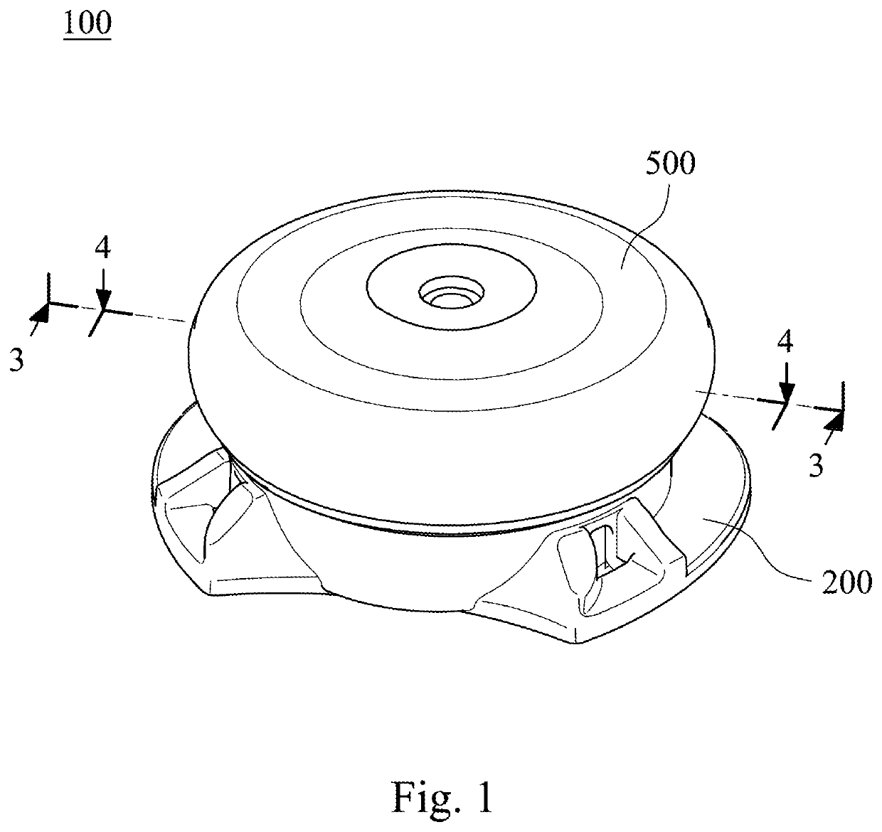
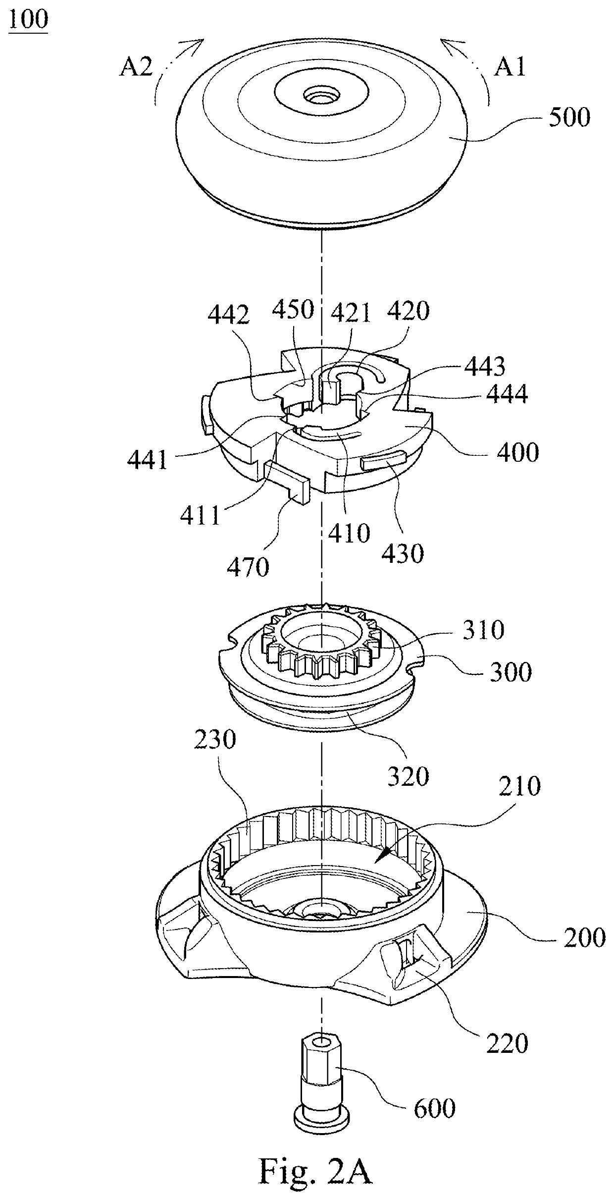
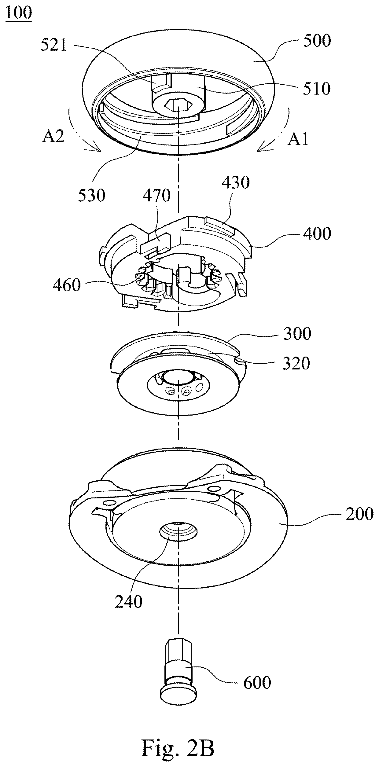
[0036]Please refer to FIG. 1, FIG. 2A and FIG. 2B, wherein FIG. 1 shows a three-dimensional schematic view of a fastening device 100 according to one embodiment of the present disclosure, FIG. 2A shows one exploded view of the fastening device 100 of FIG. 1, and FIG. 2B shows another exploded view of the fastening device 100 of FIG. 1. The fastening device 100 includes a base 200, a spool 300, a knob 500 and an engaging unit 400, the spool 300 is disposed at the base 200 and a lace (not shown) is wound therearound, the...


PUM


Abstract

A fastening device includes a main part and a fastening member. The main part is composed of a base, a spool, a knob and an engaging unit. The fastening member disposed at the main part. The spool is disposed at the base. The knob disposed at the base includes a spiral track. The engaging unit coupled to the spool includes a guiding portion coupled to the spiral track. The guiding portion is limitedly moved along the spiral track by rotating the knob such that the engaging unit has a first position and a second position relative to the knob. The engaging unit prohibits the spool from rotating toward a releasing direction when the engaging unit is at the first position, and the engaging unit allows the spool to be rotated toward the releasing direction when the engaging unit is at the second position.

Description

RELATED APPLICATIONS[0001]This application is a continuation of International application No. PCT / CN2016 / 106648, filed Nov. 21, 2016, which claims the benefits of priority of CN application No. 201510995848.7 filed on Dec. 25, 2015, the content of which are incorporated herein by reference.BACKGROUNDTechnical Field[0002]The present disclosure relates to a fastening device, and more particularly, the present disclosure relates to a fastening device for tightening and releasing a lace.Description of Related Art[0003]In daily life, cords, such as a lace or a thread, are usually used to tighten articles. The most common tightening method is to use the cord to reciprocately pass through holes on the article, such as eyelets of a shoe, and then tie a knot to secure the article. But in this kind of tightening method, the knot is loosened easily because of an external force. Not only does the knot need to be tied again, but also lots of inconveniences come owning to the insecurity of the ar...

Claims


Application Information

Patent Timeline
Patent Type & Authority Patents(United States)
IPC IPC(8): A43C7/00B65H75/44A43C11/00A43C11/16B65H75/36
CPCA43C11/008A43C11/165B65H75/4402A43C7/00B65H75/364G05G1/12B65H75/34
Inventor CHEN, CHIN-CHU
Owner CHEN CHIN CHU
Why Eureka
Try Eureka