Unit cell module and gasket for polymer electrolyte fuel cell

a fuel cell and polymer electrolyte technology, applied in the field of fuel cells, can solve the problems of low sealing performance, reduced stack size and space, fastening pressure, etc., and achieve the effect of reducing the size of the stack, reducing the fastening force of the stack, and reducing the reaction for

Active Publication Date: 2015-02-24
PANASONIC INTELLECTUAL PROPERTY MANAGEMENT CO LTD
View PDF16 Cites 0 Cited by
  • Summary
  • Abstract
  • Description
  • Claims
  • Application Information

AI Technical Summary

Benefits of technology

[0040]As has been described in the foregoing, the polymer electrolyte fuel cell gasket of the present invention can implement a space-saving double seal that invites low reaction force. Therefore, it becomes possible to realize a reduction in the fastening force of the stack, and to reduce the stack in size. Further, it exhibits the effect that the stack can stably be fastened, that the doubled sealing performance as compared to the conventional example can be exhibited, and that the fastening structure can be simplified.

Problems solved by technology

However, in meeting the demand for a double seal between the combustible gas and the outside air for ensuring safety, the fuel cell-use gaskets of Patent Documents 1 to 6 fail to solve a plurality of issues, such as a reduction in the size and space of the stack, a reduction in fastening pressure, and maintenance of an ensured sealing performance.
In particular, with Patent Document 1, a low sealing performance is exhibited because the lips are too small for retaining a double-ensured sealing performance.

Method used


Image

  • Unit cell module and gasket for polymer electrolyte fuel cell
  • Unit cell module and gasket for polymer electrolyte fuel cell
  • Unit cell module and gasket for polymer electrolyte fuel cell

Examples


first embodiment

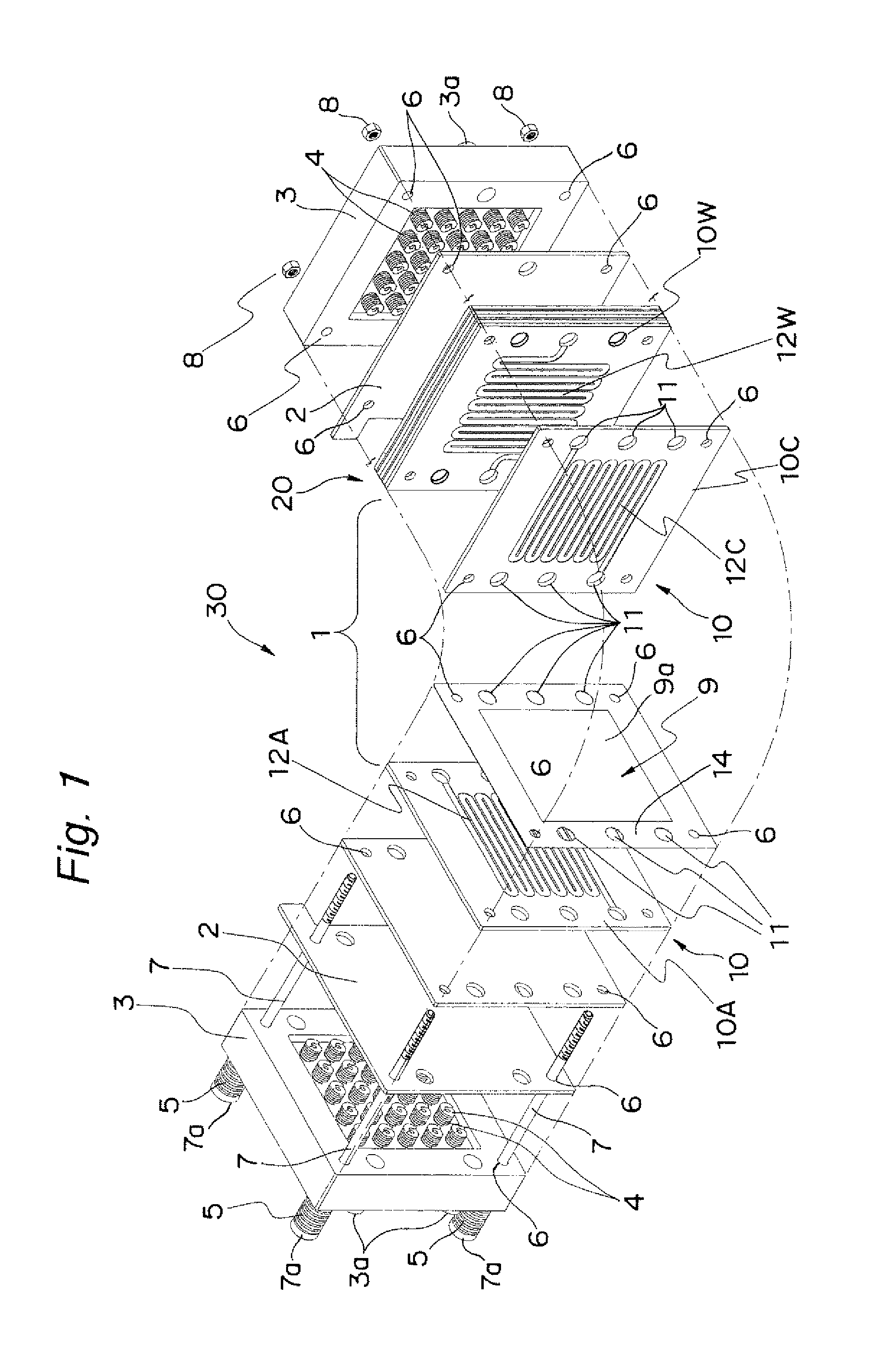
[0072]FIG. 1 is a perspective view schematically showing the structure of a fuel cell stack 30 being one example of a polymer electrolyte fuel cell (PEFC) according to a first embodiment of the present invention in a partially exploded manner. As shown in FIG. 1, the fuel cell stack 30 includes, at its central portion, a cell stacked product 20 which is made up of a plurality of unit cell modules (cells) 1 being stacked. It is to be noted that, at the outermost layer of each of both the end portions of the cell stacked product 20, a current collector 2 and an end plate 3 are disposed, the end plate 3 having on its inner plane a multiple internal springs 4 as one example of the elastic body. Four fastening bolts 7 each having an external spring 5 fitted to their respective head portions 7a penetrate from one end portion of the cell stacked product 20 through bolt holes 6 formed at the corners of each of the end plate 3, the current collector 2, the cell stacked product 20, the curren...

second embodiment

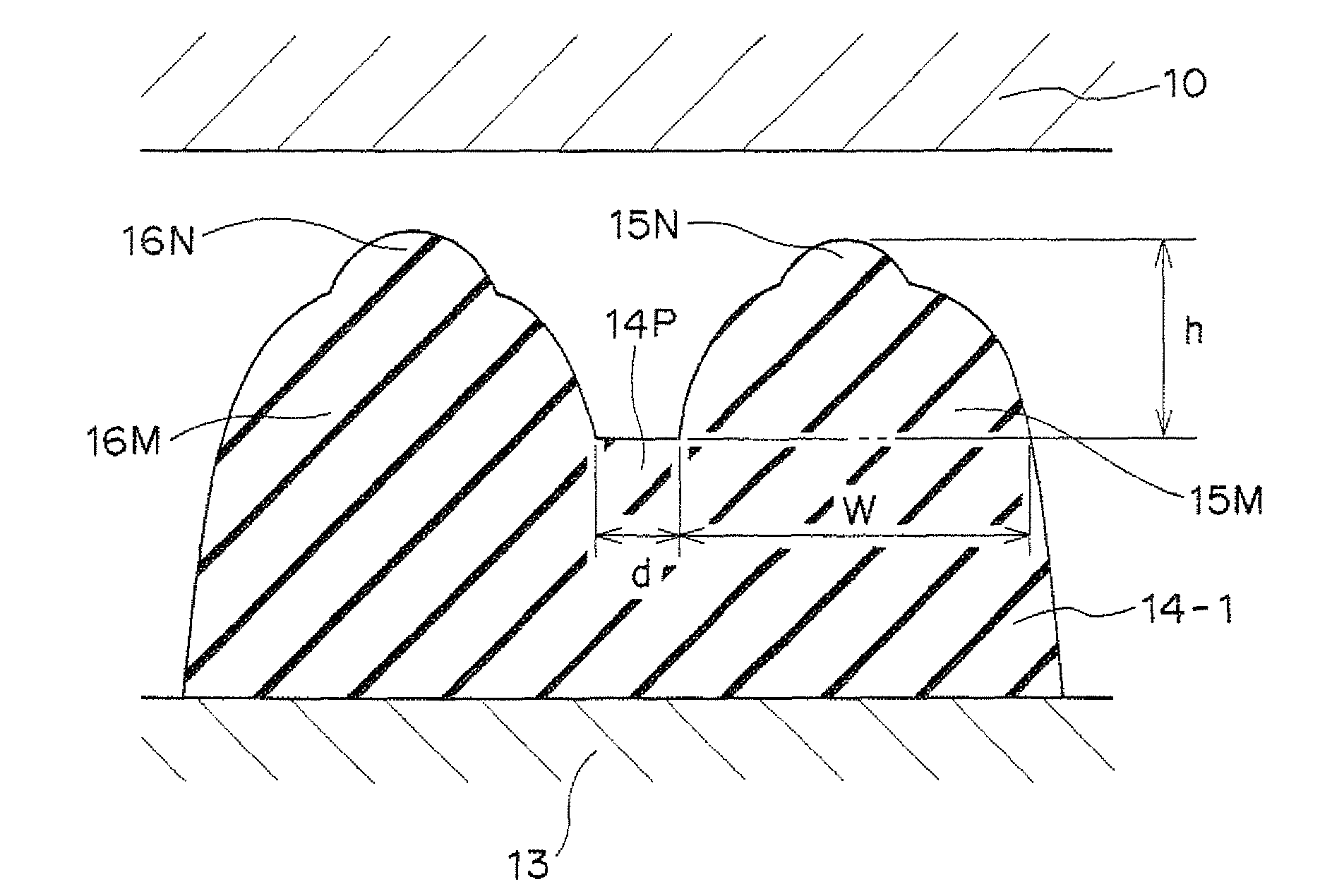
[0114]FIG. 6A shows a partial cross-sectional view of a seal structure according to a second embodiment of the present invention. While the first sealing lip 15 on the outside air side has the two-stepped lip structure which is identical to that in the first embodiment, a third sealing lip 18 on the MEA side has the single-stepped lip structure. The third sealing lip 18 may be bell-shaped with one apex in the vertical cross-sectional circular shape, instead of being the two-stepped bell-shaped. In this manner, in a situation where the inside and the outside are differing in environment from each other, by employing the sealing lip shape suitable for the corresponding environment, depending on the operation condition or the environmental condition, it becomes possible to achieve the effect of a further improvement in the sealing performance for a long period in addition to the effect of the first embodiment. This is described in the following. It is to be noted that, FIG. 6A shows th...

third embodiment

[0117]FIG. 7A is a partial cross-sectional view of a seal structure according to a third embodiment of the present invention. The gasket 14 has a two-stepped bell-shaped structure, in which the second sealing lip 16 on the MEA 9 side is two-stepped. The sealing lip 17 on the outside air side is plate-like, while the facing counter separator 10A or 10C is provided with a convex portion 24 which is in a vertical cross-sectional circular shape and convex-shaped. Similarly to the second embodiment, the ensured sealing performance can be retained by the second sealing lip 16, and further, it becomes possible to secure the sealing performance with the sealing lip 17 on the outside air side and the convex portion 24 using a small fastening force. Further, depending on the material or the internal or the external environment, it is also effective to dispose the sealing lip 17 of the plate-like structure on the inner side, and to employ the two-stepped bell-shaped second sealing lip 16 on th...


PUM

PropertyMeasurementUnit
vertex angleaaaaaaaaaa
thicknessaaaaaaaaaa
vertex angleaaaaaaaaaa

Abstract

A polymer electrolyte fuel cell-use gasket, included in a polymer electrolyte fuel cell including a fuel cell stack is provided. In the fuel cell stack, a plurality of unit cell modules is stacked, and each of the unit cell modules includes sealing members disposed at circumference portions of respective front and back surfaces of a membrane electrode assembly, and paired separators sandwiching the membrane electrode assembly and the sealing members. The sealing members are integrally molded with the circumference portions of the respective front and back surfaces of the membrane electrode assembly. In each sealing member of the gasket, two rows of sealing lips are continuously provided in parallel to each other in an in-plane manner, and at least an outer one of the two rows of sealing lips is integrally formed, having a top side bell-shaped portion overlaid on a bottom side bell-shaped portion.

Description

TECHNICAL FIELD[0001]The present invention relates to a fuel cell used for a portable power supply, an electric vehicle-use power supply, a household cogeneration system, or the like. In particular, the present invention relates to a gasket for a polymer electrolyte fuel cell using polyelectrolyte.BACKGROUND ART[0002]A fuel cell using polyelectrolyte allows a hydrogen-containing fuel gas and an oxygen-containing oxidant gas, such as air, to electrochemically react with each other, such that electric power and heat are generated at the same time. The fuel cell is basically structured with a polymer electrolyte membrane that selectively transports hydrogen ions, and paired electrodes formed on both the surfaces of polymer electrolyte membrane, i.e., the anode and the cathode, respectively. These electrodes each have a catalyst layer whose principal component is carbon powder bearing platinum metal catalyst and which is formed on the front surface of the polymer electrolyte membrane, a...

Claims


Application Information

Patent Timeline
Patent Type & Authority Patents(United States)
IPC IPC(8): H01M8/24H01M2/20H01M8/02H01M8/10
CPCH01M8/242H01M8/0273H01M8/0276H01M8/0286H01M8/0284H01M8/248H01M2008/1095Y02E60/50H01M8/0263H01M8/0267H01M8/2483
Inventor YAMAMOTO, YOKOMATSUMOTO, TOSHIHIROMORIMOTO, TAKASHIYOSHIMURA, MITSUO
Owner PANASONIC INTELLECTUAL PROPERTY MANAGEMENT CO LTD
Why Eureka
Try Eureka