Joint structure and boot for joint

A joint structure and joint cover technology, which is applied to elastic couplings, mechanical equipment, couplings, etc., can solve problems such as damage, and achieve the effect of reducing the number of parts and light weight

Inactive Publication Date: 2008-08-27
HONDA MOTOR CO LTD
View PDF4 Cites 4 Cited by
  • Summary
  • Abstract
  • Description
  • Claims
  • Application Information

AI Technical Summary

Problems solved by technology

Therefore, if the small-diameter tube 7 is repeatedly stripped, the portion of the joint cover 5 that abuts against the metal band 9 may be damaged

Method used


Image

  • Joint structure and boot for joint
  • Joint structure and boot for joint
  • Joint structure and boot for joint

Examples


Embodiment Construction

[0062] Preferred embodiments of the joint structure and the joint cover according to the present invention will be described in detail below with reference to the accompanying drawings.

[0063] First, the joint structure, which serves as a driving force transmission mechanism for transmitting the driving force from the engine to the tires, will be described below.

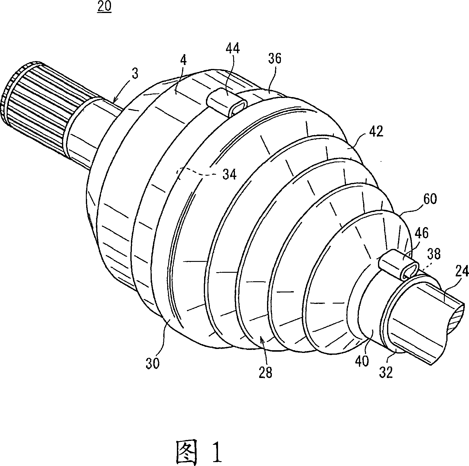
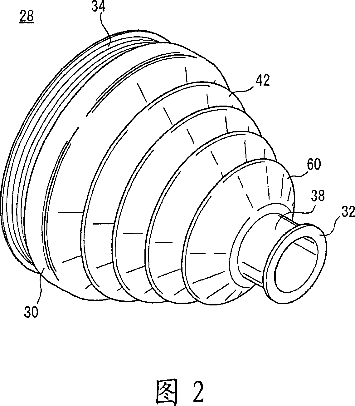
[0064] FIG. 1 is a schematic partial perspective view of a joint structure 20 (driving force transmission mechanism) according to an embodiment of the present invention. In FIG. 1, reference numerals 3, 24 denote a cage type constant velocity joint and a spline shaft of a differential gear, respectively. The joint cover 28 is mounted on a part of the outer member 4 of the CV joint 3 and the end of the spline shaft 24 and extends therebetween.

[0065] The cage-type constant velocity joint 3 includes: an outer member 4 having a substantially hemispherical shape with an opening (not shown); and an inner member (not...


PUM


Abstract

A flexible section (56) is provided between a small-diameter tube section (32) and a bellows section (42) of a boot (28) for a joint, and the flexible section (56) has a greater flexibility than the small-diameter tube section (32). When a spline shaft (24) is displaced so as to incline relative to a constant velocity joint (3), deformation stress acting in the boot (28) is relaxed by allowing the flexible section (56) to deflect (bend). This inhibits the inner wall surface of the small-diameter tube section (32) from separating from the sidewall surface of the spline shaft (24).

Description

technical field [0001] The present invention relates to a joint structure including a constant velocity joint and a shaft, and to a joint cover for protection surrounding a joint between the constant velocity joint and the shaft. Background technique [0002] Automobiles are propelled by rotating tires by rotational driving force generated by, for example, internal combustion engines, electric motors, etc. and transmitted from differential gears to hubs through multiple transmission shafts, such as half shafts, spline shafts, and the like. The drive shafts are connected to each other by constant velocity joints. [0003] A joint structure 1 shown in FIG. 19 includes a cage-type constant velocity joint 3 through which a spline shaft 2 is connected to a not-shown hub. The CV joint 3 includes a hollow outer member 4 having an open end, and a joint cover 5 is mounted on the outer member 4 and the ends of the spline shaft 2 and extends therebetween. The joint cover 5 serves as ...

Claims


Application Information

Patent Timeline
Patent Type & Authority Applications(China)
IPC IPC(8): F16D3/84
Inventor 山本雅史
Owner HONDA MOTOR CO LTD
Why Eureka
Try Eureka