
Metal gasket

a metal gasket and gasket technology, applied in the direction of engine sealing, machine/engine, engine sealing arrangement, etc., can solve the problems of fuel consumption deterioration, increased material cost, fuel consumption deterioration, etc., to reduce material cost, reduce fastening force, and high sealing performance

Inactive Publication Date: 2011-06-14
NICHIAS CORP
View PDF11 Cites 4 Cited by
  • Summary
  • Abstract
  • Description
  • Claims
  • Application Information

AI Technical Summary

Benefits of technology

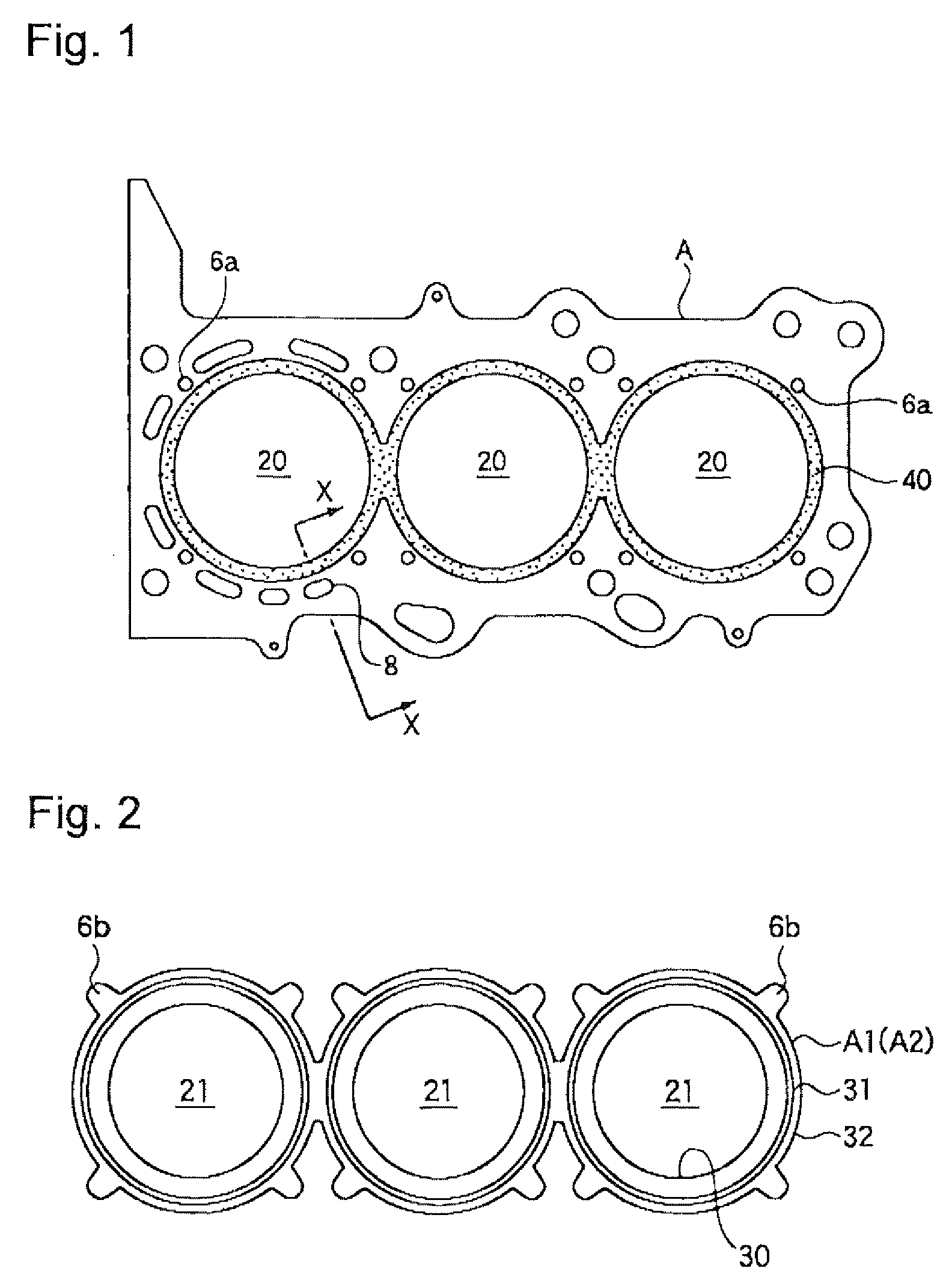
[0008]The invention has been made in view of the above-mentioned problems, and an object of the invention is to provide a metal gasket which gives sufficient sealing performance in spite of low fastening force, does not bring about deformation of a bore portion of a cylinder block, and can be produced at low cost.
[0030]are formed. Therefore, the invention provides high sealing performance, decreased fastening force and no occurrence of deformation of a bore portion of a cylinder block. Further, a pair of the elastic metal substrates are required to be formed only on the periphery of the bore portion, so that the material cost can be decreased.

Problems solved by technology

Consequently, an excessive pressing force is applied to a joint surface of the cylinder block with respect to the cylinder head to thereby bring about deformation of the bore portions in some cases, and there is the possibility of causing deterioration of fuel consumption or the like.
For these reasons, this technique involves a problem of an increased material cost.
This change causes friction between the cylinder head and the piston, and results in deterioration of fuel consumption as well.
However, commercially available thin metal plates are poor in selectivity by thickness, and the unit of the thickness is from 0.05 to 0.1 mm.
It is therefore impossible to perform fine adjustment of the surface pressure.

Method used


Image

  • Metal gasket
  • Metal gasket
  • Metal gasket

Examples


example 1

[0073]Both surfaces of a metal substrate having a thickness of 0.25 mm were coated with a rubber compound obtained by incorporating a sulfur-based crosslinking agent and crosslinking coagent and a heat decomposable foaming agent in NBR, and dissolving the resulting mixture in toluene to form a foamed rubber layer having a thickness after drying of 150 μm, thereby preparing a thin metal plate.

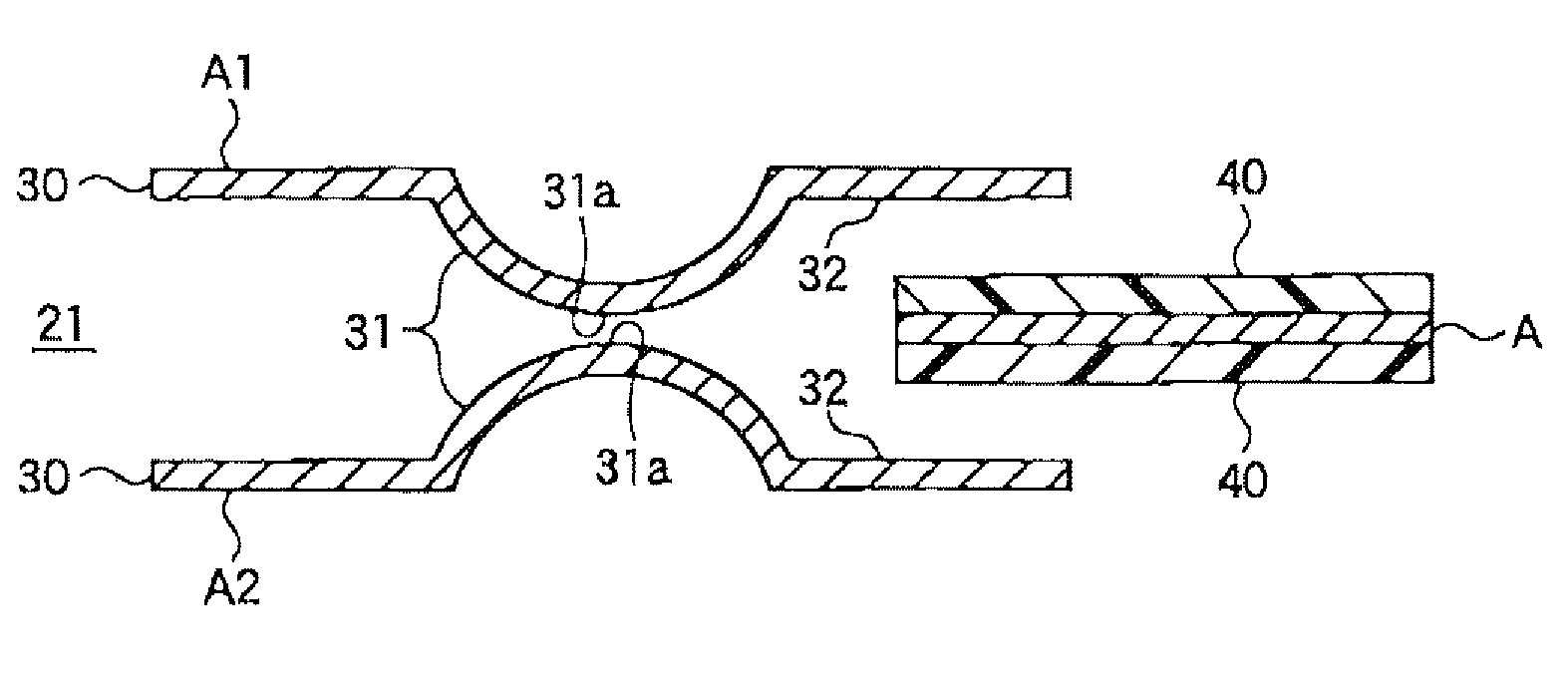
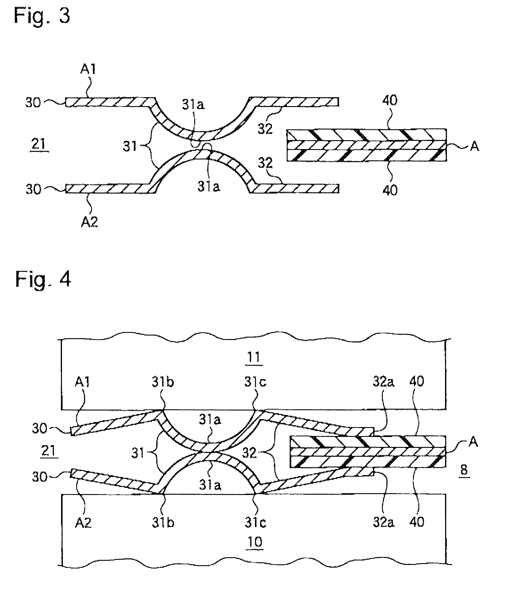
[0074]Further, using stainless steel plates having a thickness of 0.2 mm, elastic metal substrates having the cross sectional shape shown in FIG. 3 were prepared. The length from the opening edge portion 30 to the edge portion 31b of the convex portion 31 was taken as 1.0 mm, the convex portion 31 was smoothly rounded taking the distance between 31b and 31c as 3.0 mm and the height of the top portion 31a as 0.1 mm, and the length of the holding portion 32 (the distance from the edge portion 31c to the edge portion 32a) was taken as 10 mm.

[0075]Then, the thin metal plate was held between a pair o...

example 2

[0076]Using stainless steel plates having a thickness of 011 mm, elastic metal substrates having the cross sectional shape shown in FIG. 5 were prepared. The length from the opening edge portion 30 to the edge portion 31b of the convex portion 31 was taken as 1.0 mm, the convex portion 31 was formed taking the distance between 31b and 32c as 1.5 mm, the height of the top portion 31a as 0.1 mm, the length of the planar portion 33 as 1 mm, the length of the inclined portion 34 as 1.5 mm and the length of the holding portion 32 (the distance from the edge portion 31c to the edge portion 32a) as 10 mm. Further, the convex portion 31 was the same as the holding portion 32 in height.

[0077]Then, a metal substrate having a thickness of 0.2 mm on both sides of which foamed rubber layers having a thickness after drying of 100 μm had been formed was held between a pair of the elastic metal substrates prepared to form a metal gasket, which was mounted between joint surfaces of an actual cylinde...


PUM


Abstract

The present invention provides a metal gasket to be fitted between a cylinder head and a cylinder block to seal a gap between the surfaces thereof, which comprises: a thin metal plate with an opening formed at a position corresponding to a bore portion of the cylinder block, the opening having a diameter larger than that of the bore portion; and a pair of elastic metal substrates each having: an opening which substantially agrees with the bore portion of the cylinder block; an annular convex portion formed concentrically with the opening at a position apart from an edge portion of the opening by a specified distance; and an annular holding portion for holding a peripheral portion of the opening of the thin metal plate, horizontally extending out from an outer edge portion of the convex portion, wherein the pair of the elastic metal substrates are disposed so that top portions of the respective convex portions face each other and that the holding portions overlap with the thin metal plate, and engaged to the thin metal plate at a plurality of positions.

Description

FIELD OF THE INVENTION[0001]The present invention relates to an improvement of a metal gasket to be fitted between a cylinder block and a cylinder head of an internal combustion engine.BACKGROUND OF THE INVENTION[0002]In an internal combustion engine, a metal gasket is interposed between joint surfaces of a cylinder block and a cylinder head, followed by fastening, thereby imparting a sealing function. In particular, sealing in a region surrounding a bore portion of the cylinder block is important, and insufficient sealing in this portion causes a pressure drop in a combustion chamber and overheat. Consequently, a metal gasket which is constituted such that a thin metal plate having an opening corresponding to the bore portion is held between a pair of elastic metal substrates provided with beads concentric with the bore portion to enhance the sealing function of a peripheral portion surrounding the bore portion by utilizing repulsive force of the bead generated when the whole is fa...

Claims


Application Information

Patent Timeline
Patent Type & Authority Patents(United States)
IPC IPC(8): F02F11/00F16J15/08
CPCF16J15/0825F16J2015/0862
Inventor MURATA, TAKESHIYASUDA, MANABUTANAKA, SATOSHI
Owner NICHIAS CORP
Learn More