
Fluid device unit structure

a technology of fluid device and unit structure, which is applied in the direction of diaphragm valves, engine diaphragms, valve housings, etc., can solve the problems of solution stagnation portion, solidification of chemical solution remaining, etc., and achieve sufficient thickness, sufficient sealing performance of the first valve, and reduced chemical solution stagnation portion.

Active Publication Date: 2014-04-29
SURPASS IND
View PDF13 Cites 6 Cited by
  • Summary
  • Abstract
  • Description
  • Claims
  • Application Information

AI Technical Summary

Benefits of technology

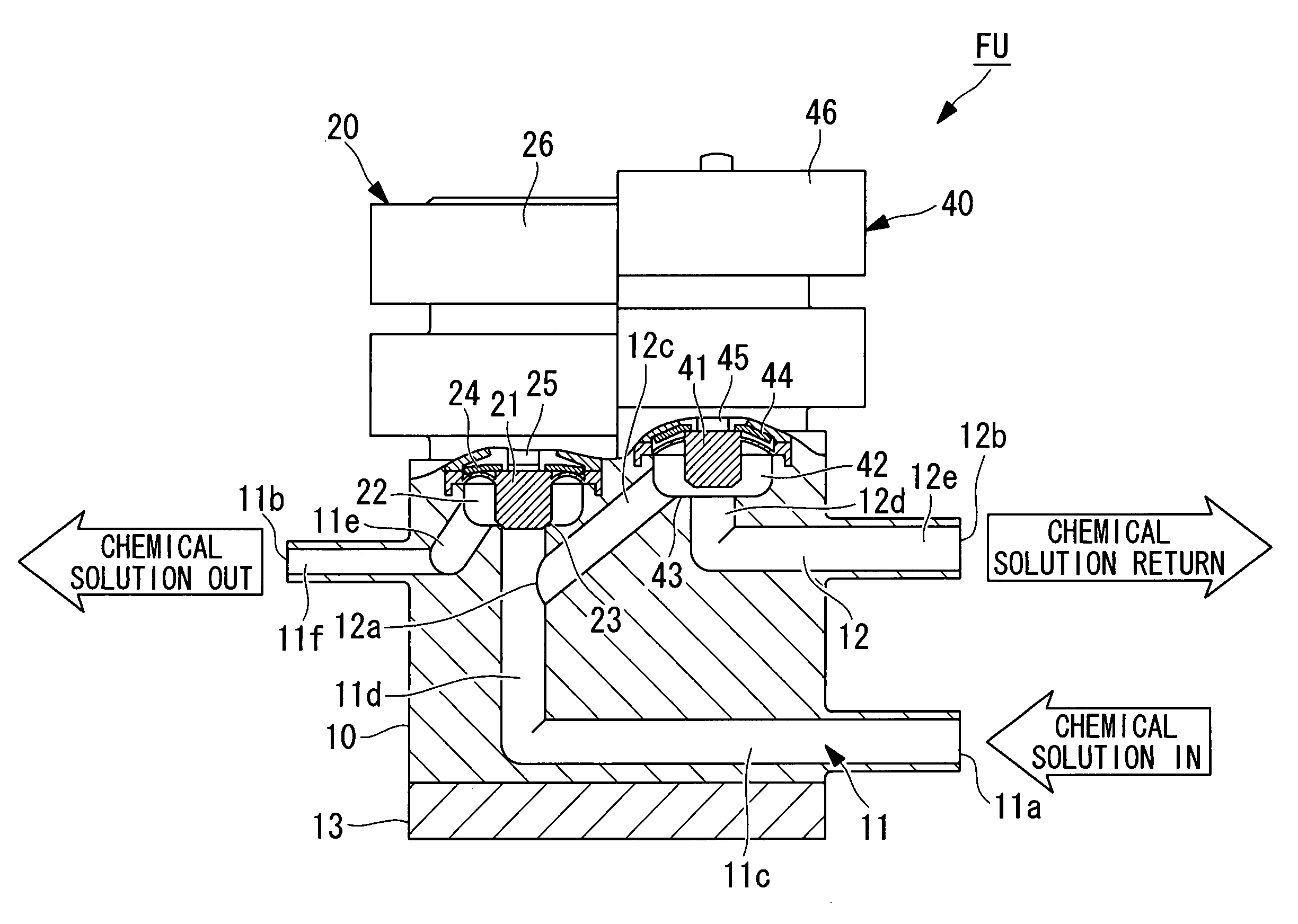
[0008]The present invention has been conceived under the above-described circumstances, and it is an object thereof to provide a fluid device unit structure that hardly causes solidification of a chemical solution by minimizing the chemical solution stagnation portion that is formed between the valve of the main fluid flow path and the branching point of the return flow path.
[0011]According to the present invention, since the position at which the return flow path branches from the main fluid flow path is close to the upstream side of the first valve, the volume (chemical solution stagnation portion) that is formed between the branching point of the return flow path and the upstream side of the first valve and that allows a liquid such as a chemical solution to remain therein can be minimized.
[0012]In the above-described invention, it is preferable that the vicinity of the upstream side of the first valve at which the return flow path branches from the main fluid flow path be a type in which the first valve moves a plug-type valve element up and down to open or close the upward-facing opening of the main fluid flow path and be a position of the base member that serves as a valve seat of the first valve and has a sufficient thickness ensuring the valve-seat stiffness. By doing so, in the state in which the first valve is completely closed by pressing the valve element against the valve seat, the chemical solution stagnation portion can be minimized while ensuring sufficient sealing performance of the first valve.
[0013]In the above-described invention, in the second valve, it is preferable that the second valve receives a liquid pressure with a diaphragm, opens and closes the return flow path by moving a plug-type valve element up and down by an open-and-close operation mechanism, and has a valve element having a base-side diameter smaller than a tip-side diameter. By doing so, a high back-pressure responsive second valve is provided. That is, by reducing the base-side diameter of the valve element and also the diaphragm diameter, the pressure (back pressure) of a liquid acting in the direction to open the valve element in the completely closed state can be reduced. Therefore, the force for pressing the valve element in the direction to close it can be decreased. Note that the open-and-close operation mechanism in such a case is, for example, operated by air pressure or an electromagnet.
[0014]According to the above-described fluid device unit structure of the present invention, the chemical solution stagnation portion that is formed between the valve of the main fluid flow path and the branching point of the return flow path can be minimized to provide a fluid device unit structure in which hardly any chemical solution solidifies. Therefore, even if the liquid to be handled is one that easily solidifies, such as a slurry-like chemical solution, prevention of the supply of chemical solution due to clogging of the main fluid flow path does not occur, or a decrease in the supply amount of chemical solution due to a reduction in cross-sectional area of the flow path does not occur. Therefore, the structure has a notable effect of enhancing the reliability of the semiconductor manufacturing process.

Problems solved by technology

In a fluid device unit structure that can switch the flow path between a case in which supply of a chemical solution (slurry) is achieved by opening the valve of the main fluid flow path and closing the valve of the return flow path and a case in which return of the chemical solution is achieved by closing the valve of the main fluid flow path and opening the valve of the return flow path, it has been a problem that a chemical solution stagnation portion is formed when the chemical solution is returned.
That is, since the path between the completely closed valve of the main fluid flow path and the branching point of the return flow path becomes a chemical solution stagnation portion that causes a liquid pool where the chemical solution hardly flows, a problem of solidification of the chemical solution remaining in the chemical solution stagnation portion has been noted.
These disadvantageously affect the semiconductor manufacturing process.

Method used


Image

  • Fluid device unit structure
  • Fluid device unit structure
  • Fluid device unit structure

Examples


Embodiment Construction

[0032]An embodiment of a fluid device unit structure according to the present invention will be described below based on the drawings.

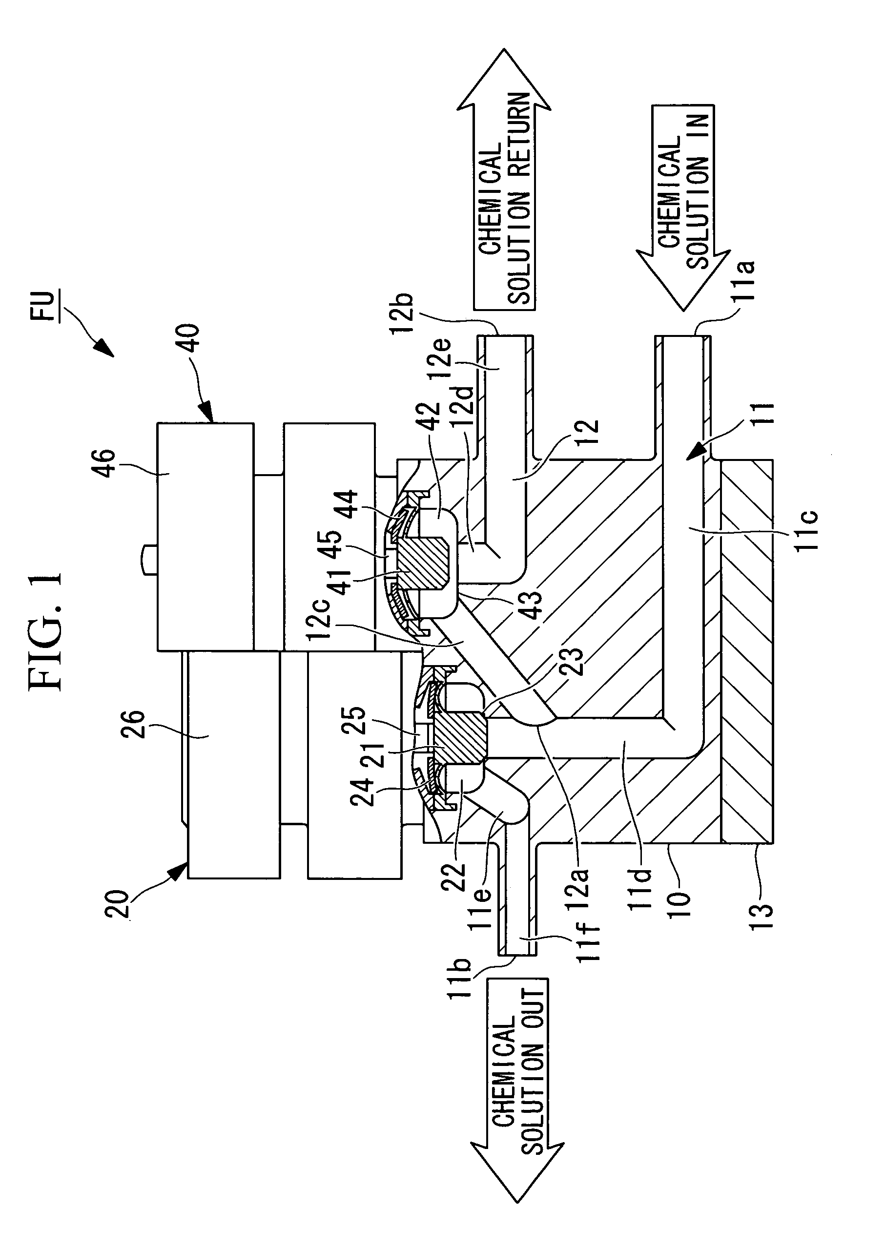
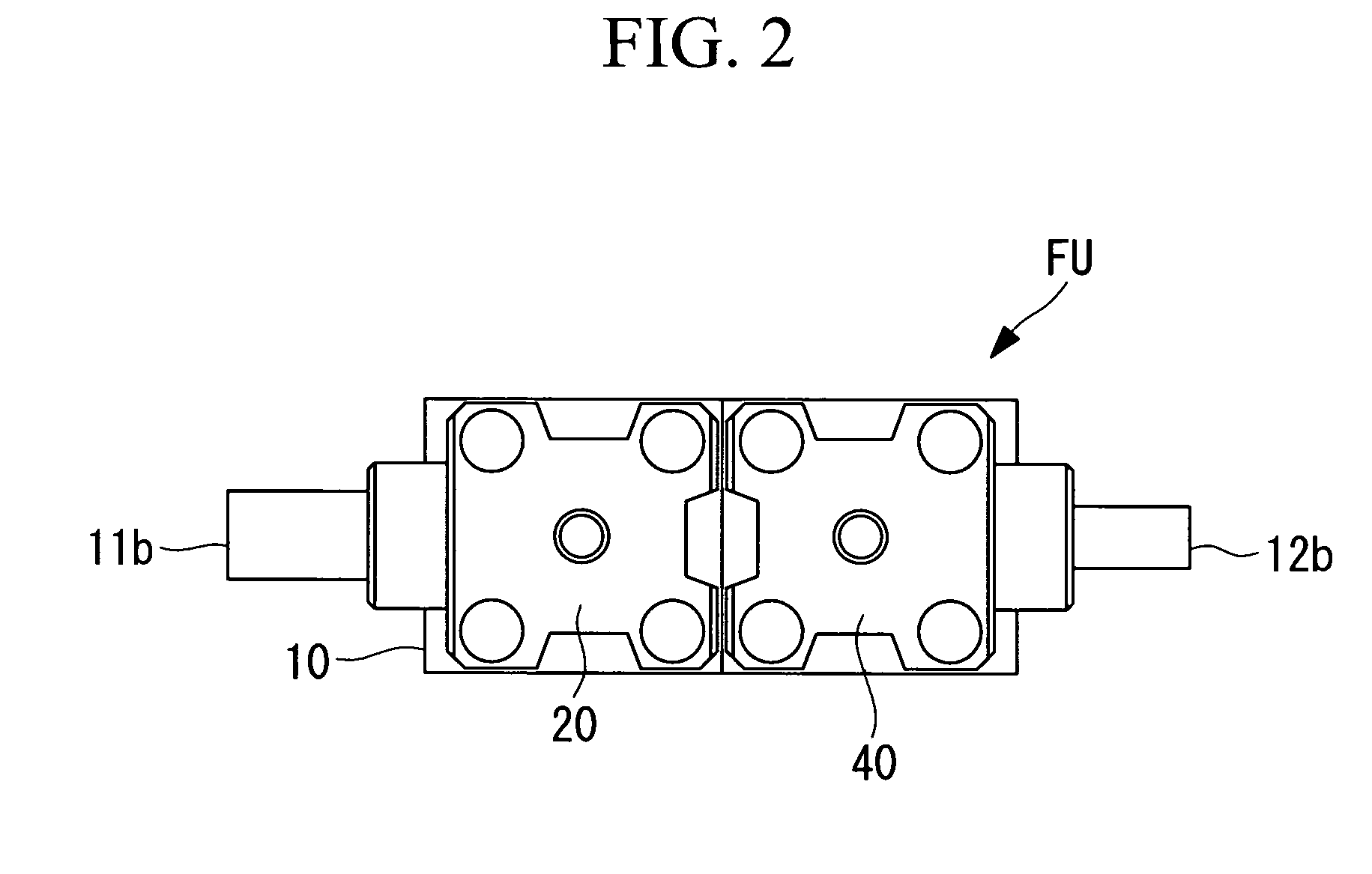
[0033]The fluid device unit structure shown in FIGS. 1 to 3 is one in which a plurality of fluid devices connected via flow paths are integrated on a base member 10 to form a single unit. In the configuration example shown in the drawings, since a chemical solution is made to flow as the fluid, a main portion (for example, a liquid contacting portion) of the fluid device unit FU is made of a chemical-resistant fluororesin. Furthermore, the fluid device unit FU employs two pneumatic valves 20 and 40 as the fluid devices, and these fluid devices are integrated on the base member 10 to form a single unit.

[0034]In the following description, the pneumatic valve of a main fluid flow path 11 formed in the base member 10 is referred to as a first valve 20, and, similarly, the pneumatic valve of a return flow path 12 formed in the base member 10 is referred to...


PUM


Abstract

Provided is a fluid device unit structure in which a chemical solution stagnation portion that is formed between a valve of a main fluid flow path and a branching point of a return flow path is minimized to cause hardly any solidification of a chemical solution. In the fluid device unit structure in which a plurality of fluid devices that are connected via flow paths are integrated on a base member (10) to form a single unit, and the main fluid flow path (11) and the return flow path (12) formed in the base member (10) are respectively provided with a first valve (20) and a second valve (40) for switching the flow paths, the branching inlet (12a) at which the return flow path (12) branches from the main fluid flow path (11) is close to the upstream side of the first valve (20).

Description

CROSS-REFERENCE TO RELATED APPLICATION[0001]This application is the U.S. national phase, pursuant to 35 U.S.C. §371, of international application No. PCT / JP2008 / 068026 published in Japanese on Apr. 16, 2009 as international publication No. WO 2009 / 048020 A1, which claims the benefit of Japanese Patent Application Ser. No. 2007-265586, filed Oct. 11, 2007, the disclosure of which applications are incorporated herein in their entireties by this reference.TECHNICAL FIELD[0002]The present invention relates to a fluid device unit structure in which fluid devices, such as a valve and a pressure switch, are integrated.BACKGROUND ART[0003]In existing apparatuses for handling fluids such as chemicals (chemical solutions), various fluid devices (for example, valves, regulators, various sensors such as pressure sensors, and various switches such as pressure switches) serving as constituent elements are connected with piping to provide an integrated fluid device unit structure (integrated struc...

Claims


Application Information

Patent Timeline
Patent Type & Authority Patents(United States)
IPC IPC(8): F16K11/22
CPCF16K11/20F16K11/22F16K27/0263Y10T137/85954Y10T137/877Y10T137/87877
Inventor IGARASHI, HIROKI
Owner SURPASS IND
Learn More